 |
|||
|
|
|||
|
|
|||
| ||||||||||
|
|
 TM 55-1730-202-14
(paragraph 19).
RESERVOIR.
Section IV. HYDRAULIC SYSTEM
(2) Release the clamp assembly (14) and re-
37. GENERAL.
move the pump from the foot assembly (12).
The hydraulic system of the tripod hydraulic
b. Installation.
jack consists of the pump assembly, cylinder and
ram assembly, and the connecting hose assembly,
(1) Install the pump assembly (13) on the
The pump is a reciprocating piston type unit, in-
foot assembly ( 12) and secure with the clamp
corporating ball inlet and discharge valves. Two
assembly (14).
adjustable relief valves are included to maintain
(2) Couple the hose assembly to the pump.
an operating pressure of 1750 psi. The cylinder
and ram assembly transforms the hydraulic oil
(3) Fill the reservoir with oil (paragraph
pressure of the pump into a vertical lifting force.
This is effected by the ram, which is caused to
rise by the incoming oil at the bottom of the
cylinder. An O-ring packing is used for an oil
40. CYLINDER AND RAM ASSEMBLY.
seal between the ram and the cylinder wall.
a. Removal
(1) Uncouple the quick disconnect fitting
of the nose at the pump assembly.
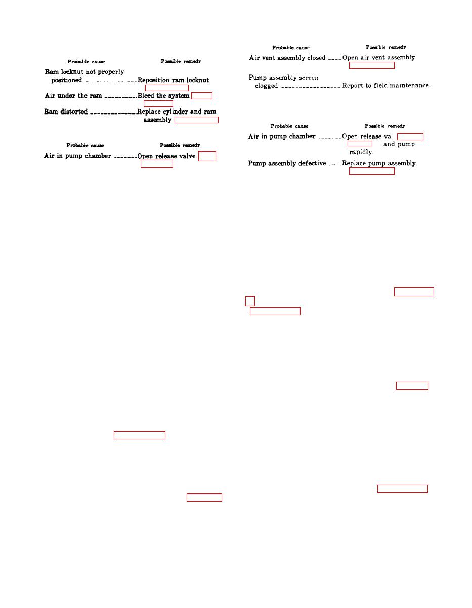
Air under the ram, indicated by springiness of
(2) Remove the nine nuts and bolts that se-
t h e ram or slowness in starting to rise, can
cure the cylinder and ram assembly (5, figure 1)
usually be removes by loosening the hose con-
ill the tripod assembly and remove the cylinder
nection at the cylinder and ram assembly and
and ram assembly.
actuating the pump. Tighten the hose connection
when the air bubbles no longer appear. If the
(3) Remove the hose assembly from the bet.
condition persists, refill the cylinder and ram
tom of the cylinder and drain the oil.
assembly with oil (paragraph 8).
b. Installation.
(1) Place the cylinder and ram assembly (5)
in the tripod assembly and secure with the 9
a. Removal.
bolts and nuts.
(1) Uncouple the quick disconnect fitting
(2) Fill the cylinder with oil (paragraph 8)
of the hose at the pump assembly (13, figure 1).
and install the hose assembly.
Section V. STRUCTURAL MEMBERS
make up the structural members of the tripod
41. GENERAL.
hydraulic jack. These members provide the firm
The tripod assembly and the three foot assem-
foundation required to support the cylinder and
blies, along with the necessary braces and links,
ram assembly during the lifting operation.
|
|
Privacy Statement - Press Release - Copyright Information. - Contact Us |
