 |
|||
|
|
|||
|
Page Title:
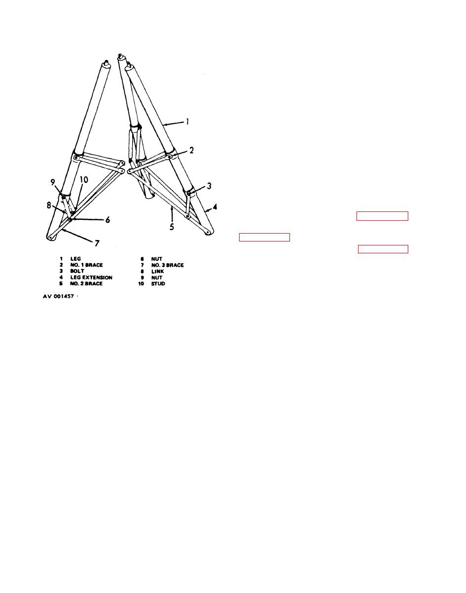
Figure 7. Tripod Assembly, Exploded View. |
|
||
| ||||||||||
|
|
 TM 55-1730-202-14
cracks and breaks by welding. Replace all parts
damaged beyond repair. Retouch or repaint as re-
quired (Federal Specification TT-E-489G, color
13538, Federal Standard 595A).
(3) Inspect all attaching hardware for distor-
tion and damaged threads. Replace all defective
parts.
d. Reassembly.
(1) Install the six leg extensions (4) on the
three legs (1).
(2) Place the six no. 3 braces (7), six no. 2
braces (5), six no. 1 braces (2), and the six links (8)
on the six leg extensions and secure with the three
studs (10), six bolts (3), and nine nuts (6 and 9).
e. Installation.
(1) Install the foot assemblies (paragraph 42).
(2) Install the cylinder and ram assembly
(3) Install the pump assembly (paragraph 39).
Change 3
17
|
|
Privacy Statement - Press Release - Copyright Information. - Contact Us |
