 |
|||
|
|
|||
|
|
|||
| ||||||||||
|
|
 TM 9-1425-600-34-5-2
NOTE
Further setting of screw (20) shall be made during test after reassembly to obtain
correct bypass pressure.
(2) Install packing (8) and backup ring (9) in groove of pump cylinder. Exercise caution to avoid damage to
either.
(3) Press wiper (10) into recess at top of pump cylinder.
(4) Drop ball (7) into cylinder and insert plunger (6).
(5) Install cotter pin (12) and plug (11).
(6) Install fulcrum (1) with link (2) and pins (3, 4, and 5).
(7) Install ball (16) and spring (15).
(8) Install pipe plug (13).
(9) Install screen (17) and packing (14) as pump is placed on jack base.
(10) With the screen and two preformed packings in place, attach pump (8, figure 3) to cylinder with the two
flathead screws (9). Tighten securely and stake at slots.
(11) Install handle (1, figure 3).
(12) Replace leg and caster assembly (paragraph 36).
AV 006462
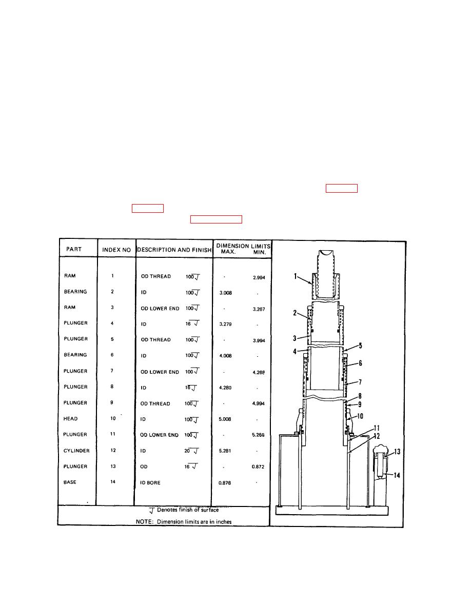
Figure 6. Table of Limits
12
|
|
Privacy Statement - Press Release - Copyright Information. - Contact Us |
