 |
|||
|
|
|||
|
|
|||
| ||||||||||
|
|
 TM 55-4920-335-14
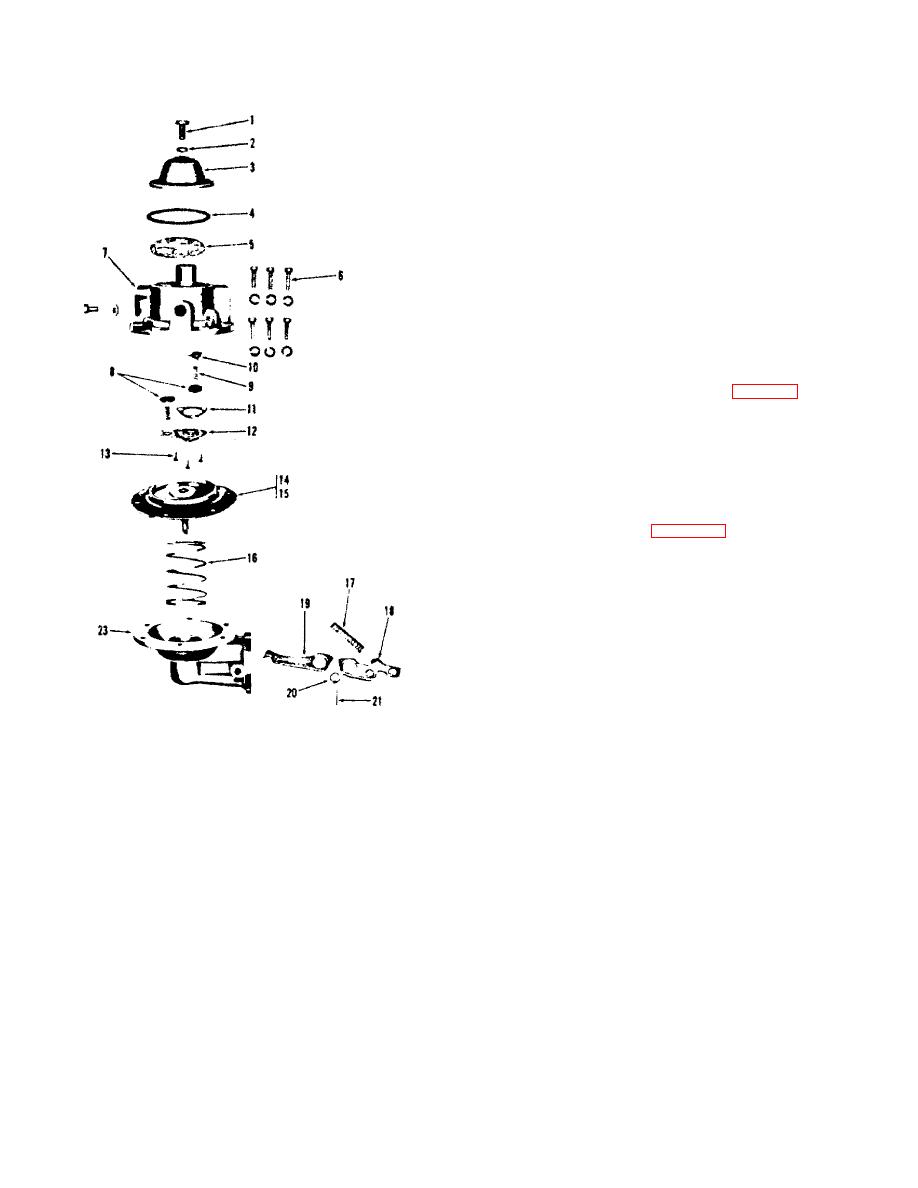
bracket (23) approximately three turns. Again crank engine
over until diaphragm (14) is pulled down into mounting bracket
(23). Tighten screws (6).
f.
Carefully clean and install filter screen (5).
g. Install gasket (4) in dome (3) and position dome onto
fuel head (7).
h. Install gasket (2) on dome bolt (1) and insert bolt in
top of dome (3) then tighten securely. Connect fuel lines and
tighten securely.
4-11. ENGINE IGNITION TIMING. If necessary to check or
retime the engine magneto, use the following procedure.
a. Remove screen over flywheel air intake opening by
taking out screws holding the screen in place. This will expose
the timing marks on flywheel and shroud (figure 4-3).
b. Remove spark plug from number 1 cylinder and turn
engine over slowly using hand crank, at the same time hold a
finger over number 1 spark plug hole so that compression
stroke can be determined by air blowing out of hole.
c. The flywheel is marked with the letters DC near one
of the air circulating vanes. This vane is further identified by an
X mark cast on the end (figure 4-3). When air blows out
number 1 spark plug hole, continue turning starting crank until
edge of marked vane on flywheel is on line with mark on
vertical centerline of shroud. Leave flywheel in this position.
At this point, keyway for mounting flywheel is also on top.
d. Remove magneto from engine. Remove fitting from
inspection hole located in gear cover at magneto mounting
flange.
e. Insert ignition cable into number 1 tower terminal of
magneto end cap and hold number 1 spark plug terminal at the
other end approximately 1/8 inch away from magneto body.
Turn magneto gear clockwise, tripping the impulse coupling
1.
Dome Bolt
13.
Screw
until number 1 terminal sparks, then hold gear in this position.
2.
Gasket
14.
Diaphragm
Install magneto on engine, meshing gears so that when
3.
Dome
15.
Gasket
magneto is in place, the gear tooth marked X will be visible
4.
Gasket
16.
Diaphragm Spring
through lower half of inspection hole in gear cover. Tighten
5.
Filter Screen
17.
Rocker Arm Spring
magneto mounting screw and nuts, making sure magneto
6.
Mounting Screw
18.
Rocker Arm
flange gasket is in place.
7.
Fuel Head
19.
Linkage
8.
Valve
20.
Rocker Arm Bushing
f. The number 1 terminal is the upper right hand tower
9.
Valve Spring
21.
Rocker Arm Pin
on the magneto cap. The terminals follow the proper firing
10.
Spring Retainer
22.
Mounting Gasket
order of 1-3-4-2 in a clockwise direction viewing the cap end.
11.
Gasket
(Not Illust)
Connect leads from magneto to spark plugs of corresponding
12.
Valve Plate
23. Mounting Bracket
number.
13.
Screw
Figure 4-2. Engine Fuel Pump
4-4
|
|
Privacy Statement - Press Release - Copyright Information. - Contact Us |
