 |
|||
|
|
|||
|
|
|||
| ||||||||||
|
|
 TM 55-4920-335-14
with that of the crankshaft. Install camshaft in crankcase. Be
sure spring and plunger are in place in end of camshaft to hold
it in position endwise. Insert tappets in proper position in
crankcase. Clean all dirt and other deposits from fins of
cylinder blocks and install them on same side of engine from
which they were removed. Tighten mounting nuts 62 to 78 foot
pounds torque.
(2) Position crankshaft in crankcase and install main
bearing plate. Use additional shims on main bearing plate if
necessary to obtain crankshaft end play of 0.002 to 0.004 inch
when engine is cold. Timing marks on crankshaft gear and
camshaft gear must match up (figure 4-10) otherwise engine
will not operate properly if timing will be off and engine will not
run. The word TOP is cast on outside of main bearing plate
and must be mounted accordingly. Mounting main bearing
plate upside down would prevent proper lubrication. Tighten
main bearing cap screws 25 to 30 foot pounds torque.
(3) Install valve assembly (figure 4-16). Be sure to
assemble roto-caps on end of valve stems. Adjust tappets
clearance should be: Inlet Valves 0.008 inch: Exhaust Valves
0.016 inch. Install valve tappet inspection plate.
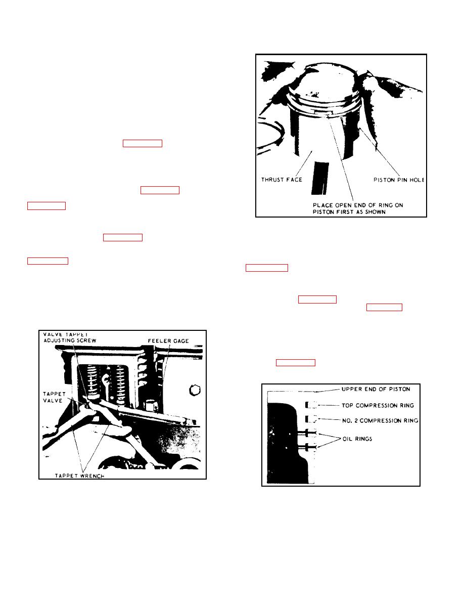
Figure 4-21. Installing Piston Rings
(4) Install piston rings by placing open end of ring on
piston first as shown in figure 4-21, spreading ring only far
(5) Place bearing shells in proper position in rod and
enough to slip over piston and into correct groove. Number 2
cap. Position caps on studs of connecting rods with identifying
compression ring must be installed with scraper edge down
number on cap on same side as number on connecting rod
pistons in cylinders. Stagger piston ring gaps 90 degrees
pounds torque then install palnuts and tighten with wrench to
1/4 turn beyond finger tight position.
cylinder walls before assembly. Be sure arrow on top of piston
(6) Position oil pump in crankcase and attach oil
is pointing in direction of crankshaft rotation (clockwise when
pump drive gear (figure 4-10) with lock nut. Tighten oil pump
viewing flywheel end). Be sure piston and connecting rod
lock screw with 5/32 inch allen wrench (figure 4-13) and install
assemblies are installed into same cylinder from which they
slotted pipe plug. Install oil pan with deep end toward oil
were removed.
pump. Tighten mounting screws 6 to 9 foot pounds torque.
(7) Install idler gear and shaft in crankcase. Be sure
oil groove in shaft is facing up. Drive shaft into crankcase with
soft metal hammer and maintain a 0.003 to 0.004 inch
clearance between idler gear and shoulder of shaft. Install
setscrew (figure 4-11) on magneto side of crankcase to lock
idler shaft in place.
Figure 4-20. Adjusting Tappets
Figure 4-22. Piston Ring Positions
4-12
|
|
Privacy Statement - Press Release - Copyright Information. - Contact Us |
