 |
|||
|
|
|||
|
|
|||
| ||||||||||
|
|
 TM 55-4920-373-14&P
4-5. TROUBLE ANALYSIS.
4-6. ELECTRICAL SYSTEM. Proceed to analyze
the following components for defects as follows:
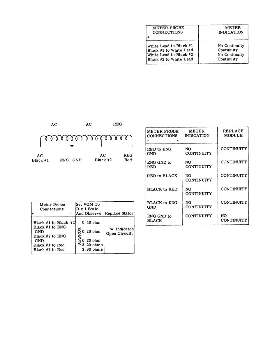
1. Ignition Wire Assembly.
a. Check ignition wire with multimeter.
NOTE
b, Check from terminal to terminal to
determine continuity. Zero reading indicates
Continuity shall be in one direction only.
broken conductor.
If readings are not as indicated, replace
2. Alternator. The alternator is comprised
module.
of the stator and rotor. The rectifier module
e. To Check Regulator Module Part No.
although external to the alternator is an integral
YJ-60 for 25 amp. The regulator module is dis-
component of the alternator.
tinguished from the rectifier module by the num-
ber and color of lead wires, and the identification
a. To Check Stator. Use an ohmmeter with
decal. The 25 amp regulator has BLACK and
R x 1 scale (minimum sensitivity of 20,000 ohms/
RED lead wires. Use an ohmmeter and static
volts), and check continuity as follows:
check continuity as follows:
NOTE
Wire numbers indicated for probe connections
are for convenience only and are not indicated
on the connectors.
b. To Check 25 Amp Stator;
4-7. HYDRAULIC SYSTEM. Perform the follow-
ing steps to determine the condition of the
hydraulic system.
1. Examine all tubing for punctures or leaks.
Stator Identification: 25 amp - 5/8" wide flange
2. Examine all couplings for signs of leakage
or corrosion.
c. To check the magnetic rotor, observe
that each separate cut between rotor electro-
Be
3. Examine hoses for punctures or leaks.
magnets are free of foreign particles, and that
especially cautious where hoses bend or rub
they are not worn down in any way.
against metal or sharp edges.
d. To check Rectifier Module, Part No.
4. Examine filters for signs of leakage or
YJ-58. The rectifier module can be distinguished
corrosion.
from the regulator by the three lead wires instead
of two and the identification decal. Use an ohmmeter
5. Start engine (Chapter II, Section IV)
and static check continuity as follows:
and perform Test 1, Test 2 and Test 3.
4-19
|
|
Privacy Statement - Press Release - Copyright Information. - Contact Us |
