 |
|||
|
|
|||
|
|
|||
| ||||||||||
|
|
 TM 55-4920-405-13&P
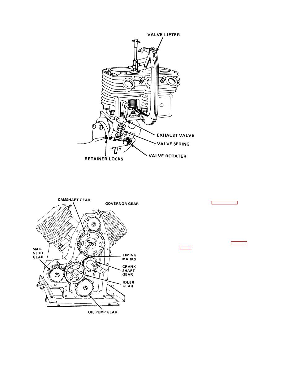
Figure 4-15.
Removal of Valves
(h)
Lift the camshaft out from the fly-
wheel end of the crankcase.
(i)
Examine all parts for damage or ex-
cessive wear. Replace all damaged
or worm parts. See figure 4-24 for
correct piston, ring, and rod
clearances.
Reassemble the crankcase assembly,
(j)
noting the following:
1.
When you are installing the cam-
shaft, make sure that the spring
and plunger are in place in the
end of the camshaft. (See figure
shaft in position endwise.
2.
Install the valve tappets after the
camshaft is installed.
3.
When you are installing the crank-
shaft, use gaskets and-shims of
the thickness needed to set the
end plate of the tapered roller
bearings at 0.002 to 0.004 inch.
4.
Make sure that you install the
main bearing plate with the word
"TOP" which is cast on the out-
side of the plate, in the up posi-
tion. If you install this plate up-
side down, the main bearing will
not be properly lubricated.
Tighten the main bearing plate
screws to a torque of 25 to 30
Figure 4-16.
Crankcase Assembly Gears
foot-pounds.
4-32
|
|
Privacy Statement - Press Release - Copyright Information. - Contact Us |
