 |
|||
|
|
|||
|
Page Title:
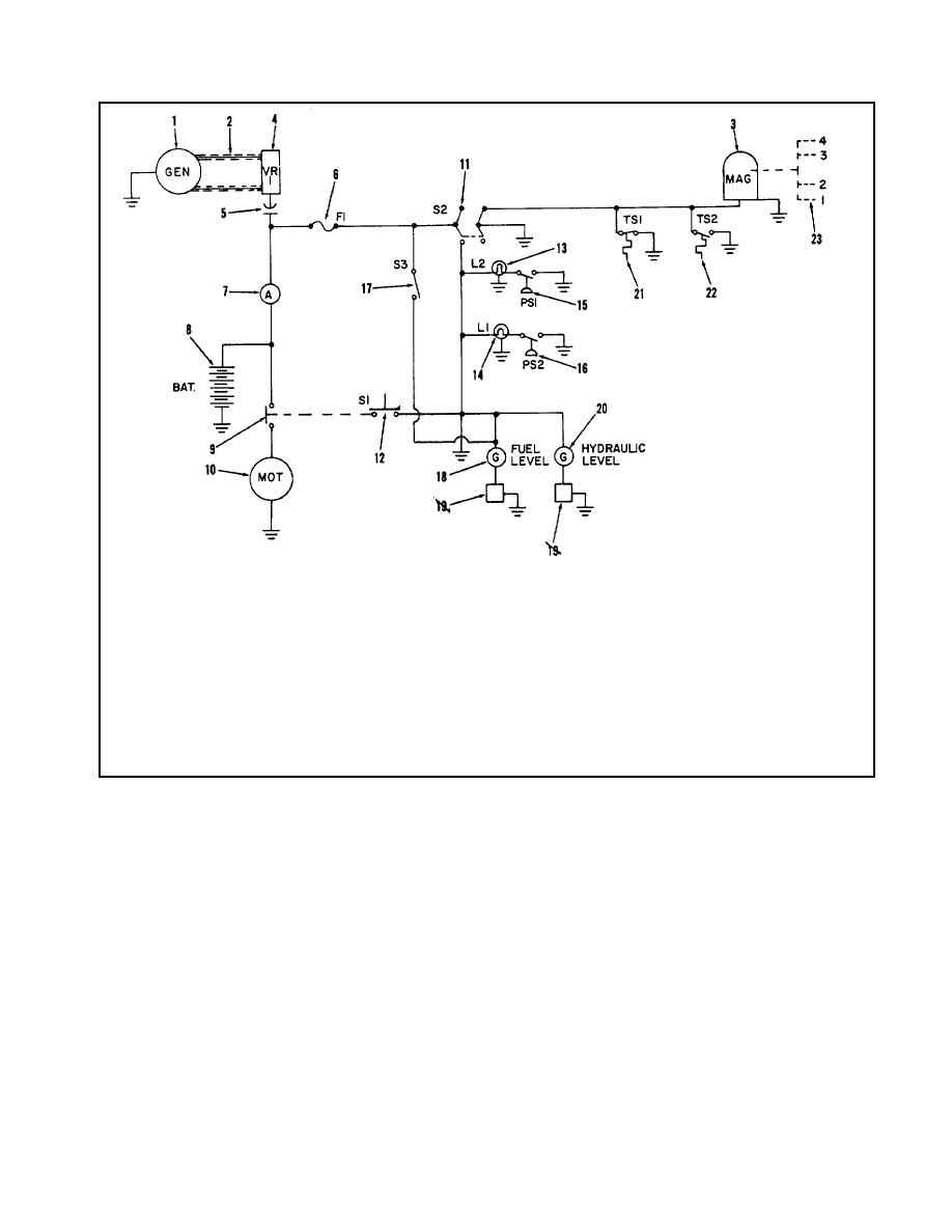
Figure 1-5. Electrical Schematic |
|
||
| ||||||||||
|
|
 TM 55-4920-335-14
1.
13.
Indicator Light L.P. Filter
2.
R.F. Connectors
14.
Indicator Light H.P. Filter
3.
Shielded Leads
15.
Differential Switch L.P.
4.
Voltage Regulator
16.
Differential Switch H.P.
5.
By Pass Capacitor
17.
Fuel Level Switch
6.
Fuse
18.
Fuel Level Gage
7.
19.
Hydraulic Oil Level Gage
8.
Battery
20.
Engine High Temp Switch
9.
Start Solenoid
21.
Hydraulic Oil High Temp Switch
10.
Start Motor
22.
Magneto
11.
Start Motor Switch
23.
Spark Plugs
12.
Ignition Switch
Figure 1-5. Electrical Schematic
and then to the aircraft on test through one of the external
panel. The high pressure filter (21) incorporates a pressure
hoses provided. Fluid is then returned to the Test Stand
differential switch (22) connected across the filter. When the
through either the 1/2 inch (27) or the 3/4 inch (26) outlet,
differential exceeds 50 pounds, the switch will illuminate a light
depending upon the outlet selector valve setting, or through the
on the control panel indicating the fault. A case drain relief
one inch return fitting (28). High pressure relief valve (20)
valve (15) set at 15 psi is installed at the high pressure pump
regulates the system pressure, dumping the excess into the
case drain outlet to provide back pressure to the pump case
return line. Fluid may also be cycled through fluid bypass
drain line for lubricity purposes. The manifold (5) is connected
valve (29). Complete instrumentation is provided on the
in the suction line and houses thermoswitch (7) which
control panel to indicate hydraulic pressure (19), suction
energizes if hydraulic fluid temperature exceeds 71 degrees C
pressure (11), hydraulic reservoir level (2) and fluid
(160F) and opens the ignition circuit stopping the engine. The
temperature (6).
A differential pressure switch (9) is
low pressure relief valve (30) is mounted on manifold (5) and is
incorporated in the low pressure filter (8) and set to actuate
used to limit maximum pressure in the hydraulic system return
when a 40 pound drop occurs across the filter. This will be
line.
indicated by the illumination of an indicating light on the control
1-7
|
|
Privacy Statement - Press Release - Copyright Information. - Contact Us |
