Order this information in Print

Order this information on CD-ROM

Download in PDF Format


Click here to make tpub.com your Home Page

Page Title: f. Installation
Back | Up | Next

Click here for a printable version

Google


Web
www.tpub.com

Home


Information Categories
.... Administration
Advancement
Aerographer
Automotive
Aviation
Combat
Construction
Diving
Draftsman
Engineering
Electronics
Food and Cooking
Math
Medical
Music
Nuclear Fundamentals
Photography
Religion
USMC
   
Products
  Educational CD-ROM's
Printed Manuals
Downloadable Books


TM 9-5130-338-12&P 4. 
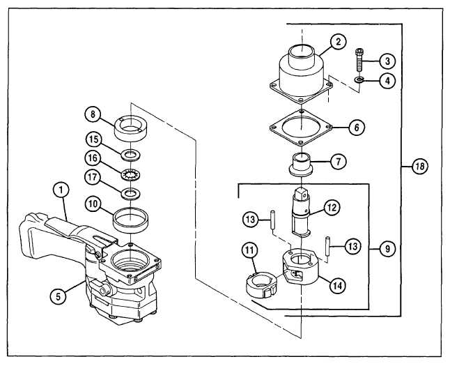
Install and secure hammer (11) in hammer frame (14) with two hammer pins (13). 5. Install anvil (12) in hammer frame assembly (9). f. Installation. 1. Aline hammer pins (13) with inertia insert (8). 2. Install hammer frame assembly (9) in main housing (5). 3. Install hammer case bushing (7), if removed, and pilot ring (10) in hammer case (2). 4. Position new hammer case gasket (6) on main housing (5). 5. Install hammer case (2) onto main housing (5) while depressing trigger (1). 6. Secure  hammer  case  (2)  to  main  housing  (5)  with  four  capscrews  (3)  and  four  new  lockwashers  (4). Torque capscrews to 180 lb-in.  (20.3 N•m). 4-9

Privacy Statement - Press Release - Copyright Information. - Contact Us - Support Integrated Publishing

Integrated Publishing, Inc. - A (SDVOSB) Service Disabled Veteran Owned Small Business