|
| |
TM 1-1730-231-13&P
3-26. FILTER - Continued
3-26
A.
INSPECTION
1.
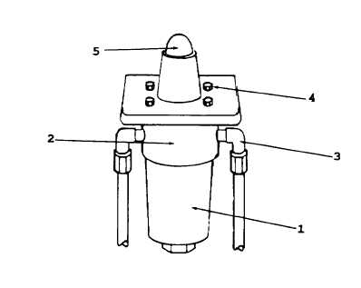
Check to see if red marker is extended in the clogging indicator.
2.
If extended, it indicates a dirty filter element in need of replacement.
B.
SERVICE
1.
Unscrew filter bowl (1) and remove.
2.
Remove filter element.
3.
Empty fluid from bowl.
4.
Clean head assembly (2) and bowl (1) with cleaning solvent P-D-680, Type II and clean cloth.
5.
Install replacement filter element, 0060D010BN/HC.
6.
Fill bowl approximately 3/4 full with hydraulic fluid and install.
C.
REMOVAL
1.
Disconnect hydraulic lines from filter. Retain straight thread elbows (3) with filter assembly.
2.
Remove four bolts (4) holding filter assembly to mounting bracket.
3.
Remove filter assembly.
4.
Remove straight thread elbows from input and output sides of filter assembly. Remove clogging indicator assembly
(5) from top of filter assembly.
5.
Discard defective filter assembly.
GO TO NEXT PAGE
3-33
|