
TM 5-2350-378-23&P
0017
REAR OF VEHICLE RAISES IN SPRUNG, BUT NOT UNSPRUNG MODE - Continued
WARNING
Do not operate ejector when personnel are in bowl. Do not work in bowl unless ejector
lock is engaged. Failure to comply may result in severe injury or death to personnel.
NOTE
All control rods are adjusted same way. This procedure covers the SPRUNG/
UNSPRUNG control rod.
a.
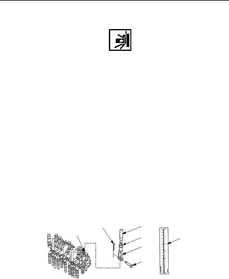
Note position of control valve plunger (Figure 6, Item 1) when SPRUNG/UNSPRUNG control lever is in
neutral (off) position.
NOTE
Normal control valve plunger travel is 9/32 in. (7mm).
b.
Remove cotter pin (Figure 6, Item 2), straight pin (Figure 6, Item 6), and clevis (Figure 6, Item 5) from
control valve plunger (Figure 6, Item 1).
c.
Discard cotter pin (Figure 6, Item 2).
d.
Loosen jam nut (Figure 6, Item 4), turn clevis (Figure 6, Item 5) clockwise to shorten rod
(Figure 6, Item 3) and counterclockwise to lengthen rod (Figure 6, Item 3) as necessary to obtain correct
valve plunger (Figure 6, Item 1) travel.
e.
Hold measuring device (Figure 6, Item 7) on face of SPRUNG/UNSPRUNG control valve.
f.
Have assistant move SPRUNG/UNSPRUNG lever between SPRUNG and UNSPRUNG mode.
g.
Measure distance of plunger travel.
h.
When rod (Figure 6, Item 3) is adjusted for desired length of travel, coat thread of rod (Figure 6, Item 3)
with sealing compound primer and sealing compound.
i.
Tighten jam nut (Figure 6, Item 4) against clevis (Figure 6, Item 5).
j.
Connect clevis (Figure 6, Item 5) to control valve plunger (Figure 6, Item 1) with straight pin
(Figure 6, Item 6) and new cotter pin (Figure 6, Item 2).
3
2
1
4
7
5
6
T01508HDC
Figure 6. SPRUNG/UNSPRUNG Control Valve Control Rod Travel.