 |
|||
|
|
|||
|
|
|||
| ||||||||||
|
|
 T.O. 35A2-2-39-11
T M 55-1730-221-12
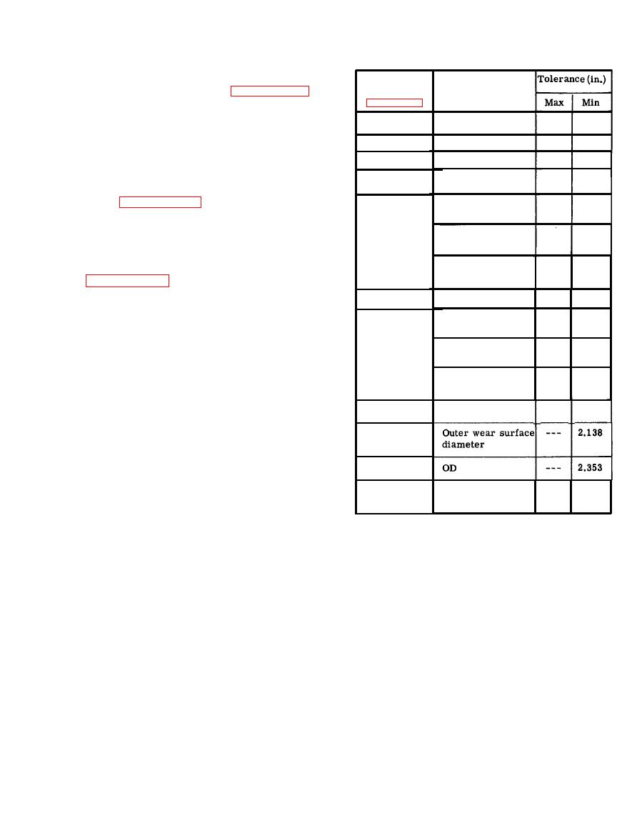
Part and
adjustments and tests outlined in paragraphs 3-11 and
Index No.
3 - 1 5 through 3-17, and shall consist of the following:
Description
a. A hydraulic or pneumatic actuating cylinder with
0.496
Minor
diameter
---
Piston (8)
a 12 ton maximum load capacity and a source of
0.507
---
ID
Nut (9)
hydraulic or air pressure equipped with an adjustable
relief valve to operate the cylinder.
0.502
---
Minor ID
B o d y (12)
b. A platform type weighing scale calibrated to
3.496
---
ID
Bushing (31)
24,000 pounds for load measurement. Mount cylinder
(refer to paragraph 3-4a) in a stationary, vertical
Outer wear surfaces
---
3.487
Ram (33)
position, and place scale directly beneath, so that
jack can be positioned between cylinder and scale.
2.991
---
Major inner wear
T h e s e components shall be positioned so that thirteen-
surface diameter
inch compression of cylinder ram is permitted.
2.793
---
Minor inner wear
surface diameter
to paragraph 3-14). Operate handle (1) to lift rams
( 3 3 , 39, 44) to contact cylinder. Adjust cylinder load-
---
3.667
Bearing (35)
OD
i n g to provide 20,000 pound (ten-ton) reading on scale.
With this load applied to jack, operate handle until
2.784
Outer wear surface
---
Ram (39)
the third-stage ram is partially extended. Visually
diameter
i n s p e c t jack for fluid leakage at pump packing nut (9),
2.364
---
Major inner wear
release valve (25), and rams. There shall be no fluid
surface diameter
leakage at any point. After test, open release valve
( 2 5 ) to lower jack.
2.147
---
Minor inner wear
surface diameter
to jack. Operate handle (1), applying force perpen-
---
2.980
OD
Bearing (41)
dicularly to axis of handle. Operating force required
during compression (downward) stroke shall be from
Ram (44)
75 to 80 pounds.
Bearing (46)
and operate handle (1) to raise rams against load.
Settling at this load shall not exceed 0.020 inch per
3.678
---
Cylinder wear
Base assem-
hour.
Perform this test twice with a 15-minute
b l y (56)
surface ID
interval between each test. Settling shall not exceed
0.005 inch at the end of each 15-minute period, a
t o t a l maximum of 0.010 inch at the end of the 30-min-
Open release valve (25) to lower jack
ute period.
Wear
Tolerance
after completion of tests.
*U.S. GOVERNMENT PRINTING OFFICE: 1993-342-421/80363
3-5 and 3-6
|
|
Privacy Statement - Press Release - Copyright Information. - Contact Us |