 |
|||
|
|
|||
|
|
|||
| ||||||||||
|
|
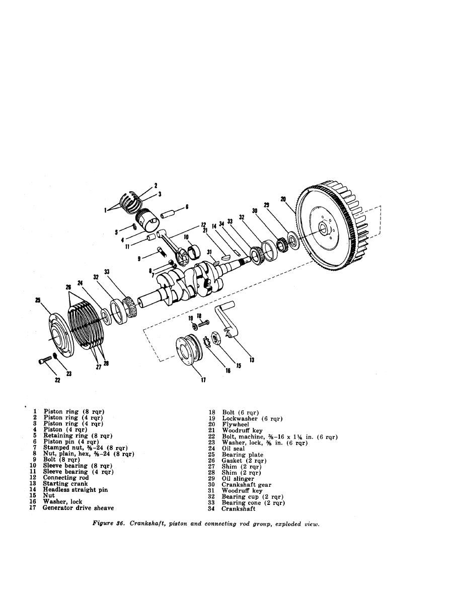
 (4) Remove the 2 stamped nuts (7), 2 hex
(5) Remove the three remaining connect-
nuts (8), and 2 bolts (9) that secure
ing rods and pistons in a similar man-
the cap of the connecting rod in place,
ner.
remove the cap and push the connect-
ing rod with attached piston (4) out
caps are marked and must be paired together
to insure correct installation.
through the top of the cylinder block.
b. Disassembly.
Reassemble the cap and bearing on
the connecting rod to prevent damage
(1) Remove the two retaining rings (5)
or loss.
and the piston pin (6) from the piston
106
AGO 5742A
|
|
Privacy Statement - Press Release - Copyright Information. - Contact Us |