|
| |
TM9-6115-667-13&P
heard. The bearing housing contains two seal check
balls which are retained by hex socket type plugs. The
hex socket plugs can be viewed from the outside of the
bearing housing (9). The check balls and hex socket
plugs are not field serviceable items and therefore, are
not shown in figure 3. The purpose of the seal balls is to
prevent oil pressure from damaging the drive shaft seals
in the event hydraulic system supply and return hoses
are connected incorrectly (see CONNECT HOSES on
page 7 of this manual). If the balls do not rattle, this may
mean they are jammed because of fluid contaminants.
Replace the bearing housing (9).
Drive Shaft (11, figure 3) and Idler Shaft (6, figure 3)
Shaft diameters at bearing and seal locations must be
smooth. Grooves, roughness or a reduced diameter
indicate fluid contamination or damaged bushings. Grit
particles may have been imbedded in the bushings
grinding into the hardened shaft. If abnormal shaft wear
as above occurs (more than normal polishing), replace
both the shaft and associated bushings.
Also
check
the
hydraulic
system
for
excess
contamination in the fluid and for filter condition.
Operating conditions may require changing from a 25-
micron filter to an oversized 10-micron filter.
RE-ASSEMBLY
• Be sure to replace all exposed seals with new parts.
• Apply clean grease or o-ring lubricant to all parts during
reassembly.
1. Carefully install the quad ring (18) into the
groove on the inside of the seal gland (16). Carefully
install the o-ring (17) onto the smaller outside diameter of
the seal gland (16) and install the seal gland into the
bore of the bearing housing (9). Replace the retaining
ring (15).
2. To replace the bearing (13) on the drive shaft
(11), support the bearing inner race and press the drive
shaft through the bearing inner race. Install the retaining
ring (14) next to the bearing on the shaft.
3. Install the bushings (3) into the housings using a
typical bearing pusher. Make sure the bushing is flush
with the surface of the bearing housing. A protruding
bushing will bind the gears.
4. Place the bearing housing (9) on a smooth clean
arbor press surface (protected from damage) TM96115-
667-13&P with the large bearing bore facing up.
Position the piece so a clearance hole exists for the
insertion of the drive shaft (11).
5. Apply grease to the drive shaft (11) and keyway;
then insert it through the seal gland (16). Using a
bearing pusher, or a sleeve/socket with a diameter of the
bearing, press the bearing and drive shaft assembly into
place. Press only on the outer race. Install the bearing
retaining ring (10).
6. Install the needle roller (12) in the keyway of the
drive shaft. Use grease to keep the needle roller in
place. Slide the drive gear (8) over the needle roller and
drive shaft. Install the idler shaft (6) and idler gear (7).
7. Apply grease to the face seal o-ring groove; then
install the o-ring (4).
8. Note the screw hole pattern on the bearing
housing (9) and the gear housing assembly (1). They
will only assemble one way. With all parts aligned,
carefully slide the gear housing assembly over the gears
until it contacts the bearing housing.
9. Turn the drive shaft (11) manually to check for
free rotation. Install the eight 1/4-20 x 2-1/4 inch/ 57 mm
long capscrews (5) and tighten to 100-120 in-lbs torque.
Recheck rotation.
10. Connect the Hyrevz motor to a hydraulic power
source and check for smooth running.
Note: Make sure the hydraulic power source is running
at the lowest gpm/lpm rate it can while still producing full
pressure.
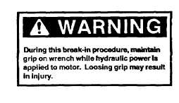
11. Hyrevz motors will sometimes be tight and require
“break-in”. Accomplish this by turning the
11
|