|
| |
TM9-6115-667-13&P
4.
Remove the idler gear (7), drive gear (8), needle
roller key (12), and the idler shaft (6).
5.
Remove the large o-ring (4) while being careful
not to damage the o-ring groove or surrounding surface.
6.
Remove the bearing housing (9) from the vise.
While protecting the mating surface from damage,
remove the retaining ring (10) from around the bearing.
Hold the bearing housing and tap lightly on the small
diameter end of the drive shaft (11) to remove it and the
bearing (13) from the front of the bearing housing.
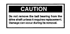
7.
To remove the bearing (13) from the drive shaft
(11), remove the retaining ring (14) on the drive shaft
next to the bearing. Press on the gear end of the drive
shaft while supporting the outer race of the bearing.
Discard the old bearing.
8.
Remove the retaining ring (15) at the bottom of
the bearing bore to service the seal gland (16), o-ring
(17) and quad ring (18). Remove the seal gland (16)
using typical o-ring service tools to pry it out of its bore.
Take care to avoid damaging the seal surfaces. Note
seal orientation. Remove the o-ring (17) from the
outside of the seal gland. Remove the quad ring (18)
from the inside of the seal gland.
9.
If the bushings (3) are to be replaced, remove
the four bushings (3) from the bearing housing (9) and
gear housing assembly (1) using a typical bushing
removal tool with a 7/16 inch collet.
INSPECTION AND CLEANING
Inspect and clean all parts as follows:
Cleaning
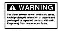
Clean all parts with a degreasing solvent. Blow dry with
compressed air and wipe clean. Use only lintfree cloths.
Gear Housing Assembly (1, figure 3)
The chamber bores and bottoms around the shaft
bushings (3) should be polished and not rough or
grooved. If the bushing bores are yellow-bronze, replace
them and investigate the cause of wear.
The flat surfaces at each end of the gear housing
assembly (1) should be flat and free of nicks or burrs that
could cause misalignment or leaks.
Bushings (3, figure 3)
The inside of the bushings should be gray with some
bronze showing through. If significant yellow-bronze
shows, replace the bushings.
Inspect drive shaft (11) for corresponding wear and
replace as required.
Gears (7 & 8, figure 3)
The drive gear (8) and idler gear (7) should have straight
tips without nicks; square tooth ends and a smooth even
polish on the teeth and end faces. Check for cracks
between the drive gear keyway and gear tooth root.
Replace the gear if cracks are present.
Bearing Housing (9, figure 3)
The
surface
near
the
gears
should
show
two
interconnecting polished circles without a step.
The bottom of the o-ring groove should be smooth as
should the rest of the flat surface.
The bore for the drive shaft seal (inside of the seal gland
[16] ) should be smooth or oil leakage may occur. The
bore in which the seal gland fits should also be smooth.
Shake the bearing housing and a rattle should be
10
|


