Home
Download PDF
Order CD-ROM
Order in Print
Figure 6. Bending large tabs with glass pliers.
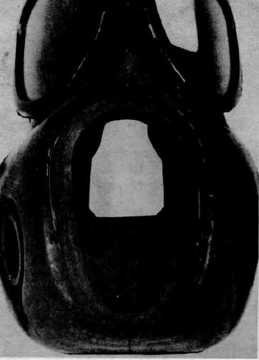
Figure 9. Expanded ring installed in nosecup.
Maintenance Manual For Crimping Outfit, Hydraulic, Voicemitter-Outlet Valve Assembly, Abc-M1
Page Navigation
3
4
5
6
7
8
9
10
11
12
13
TM
3-5180-210-15
Figure 7.
Crimping
ring
seated
around
the
voicemitter-outlet
valve
assembly
opening.
11