TM 3-5180-210-15
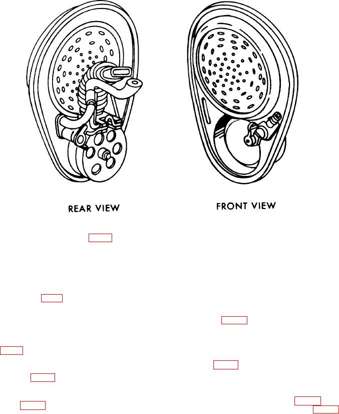
Figure 5. M1 7A1 voicemitter-outlet valve assembly.
(4) Install an expander ring (fig. 8) in the
c. Crimping.
voicemitter-outlet valve assembly opening in the
(1) Pull down on the release lever with one
nosecup. The ring holds the nosecup and facepiece
hand to release the upper die. With the other hand,
openings 'in proper alinement and position for crimping.
raise the die to its highest position.
Position the expander ring so that its smaller recess is
(2) Unlock the lower die by pushing the lower-
toward the front of the mask and its outer edge is even
die handle rearward.
with or just slightly below the surface of the nosecup
(3) Hold the mask assembly under the lower
flange. The small notch (1, fig. 9) on the expander ring
die. Fit the crimping ring in the die, and position the ring
must be alined with the mold line (2) at the top of the
against the fixed (left) side of the die. Lock the crimping
nosecup flange. Make sure that the notch on the ring,
ring in position (fig. 12) by pulling the handle forward,
the mold line on the nosecup flange, and the mold line
while observing that the right side of the die engages the
on the facepiece are alined, and that the flanges on both
crimping ring correctly.
facepiece and nosecup are seated in the bottom of the
(4) With the crimping ring locked in position,
crimping ring (fig. 9). Crimping ring tabs must extend
pull down on the release lever with one hand to release
above the flanges.
the upper die (fig. 13). At the same time, with the other
(5) Install a voicemitter-outlet valve assembly
hand, press down on the upper die until it touches the
within the crimping ring (fig. 10).
crimping ring in the lower die. Alinement pins in the
(6) Using a pair of roundnose pliers, bend
upper die will enter corresponding holes in the lower die.
one small tab at the top and one small tab at the bottom
(5) Pump the pump handle (fig. 14) until the
of the crimping ring (fig. 11) to hold the assembled parts
pressure gage indicates the preset pressure (para 6).
in position for crimping.
9

