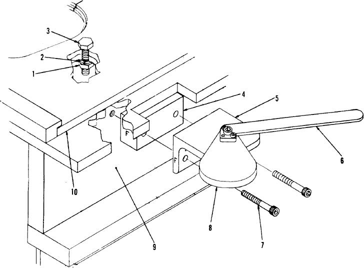
• Home
  • Download PDF
  • Order CD-ROM
  • Order in Print
CHAPTER 4 ORGANIZATIONAL MAINTENANCE INSTRUCTIONS
Figure 16. Pressure gage, hinged top oiler, and top of cylinder head.

Maintenance Manual For Crimping Outfit, Hydraulic, Voicemitter-Outlet Valve Assembly, Abc-M1
Page Navigation
  12    13    14    15    16  17  18    19    20    21    22  
img
TM 3-5180-210-15
1
Nut
6
Handle
2
Washer
7
Capscrew
3
Bolt
8
Cam
4
Spacer block
9
Support plate
5
Handle bracket
10
Lower die
Figure 15. Handle assembly, exploded view.
the shaft. The pump handle's position may be adjusted
e. Installation. Bolt the base of the hydraulic press
to suit the operator.
to the workbench.
20


Privacy Statement
Press Release
Contact

© Copyright Integrated Publishing, Inc.. All Rights Reserved.