Home
Download PDF
Order CD-ROM
Order in Print
Figure 15. Handle assembly, exploded view.
Section III. ORGANIZATIONAL PREVENTIVE MAINTENANCE SERVICES
Maintenance Manual For Crimping Outfit, Hydraulic, Voicemitter-Outlet Valve Assembly, Abc-M1
Page Navigation
13
14
15
16
17
18
19
20
21
22
23
TM
3-5180-210-15
5
Pipe
plug
(I)
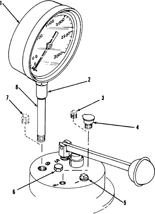
1 Pressure
gage
6
Pipe
plug
(S)
2
Pipe
coupling
7
Pipe
plug
(G)
3
Pipe
plug
(F)
8
Pipe
nipple
4
Hinged
top
oiler
Figure
16.
Pressure
gage,
hinged
top
oiler,
and
top
of
cylinder
head.
21