
TM 5-2350-378-23&P
0002
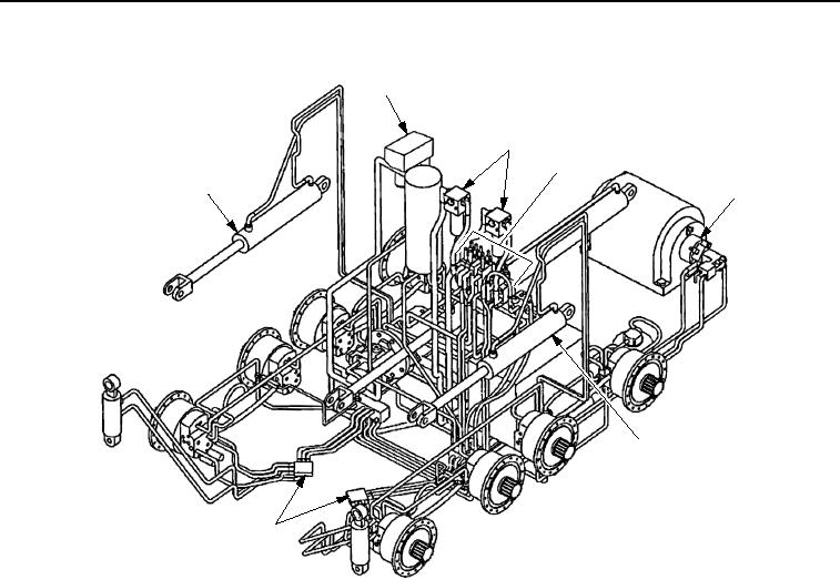
LOCATION AND DESCRIPTION OF MAJOR COMPONENTS - Continued
2
3
4
1
5
1
6
T0001HDC
Figure 3. M9 ACE Hydraulic System Major Components.
1. APRON CYLINDER (Figure 3, Item 1). Raises and lowers apron and dozer assembly (one each side).
2. RETURN LINE FILTER (Figure 3, Item 2). Filters out contaminants from hydraulic oil that is returning to
reservoir.
3. HIGH PRESSURE FILTERS (Figure 3, Item 3). Two high-pressure filters located directly in front of operator's
compartment filter hydraulic fluid from the main hydraulic pump while it is enroute to the DCV bank.
4. DIRECTIONAL CONTROL VALVE (DCV) BANK (Figure 3, Item 4). Activated by mechanical linkages from
the operator's controls to activate hydraulic functions in the vehicle. Controls direction of fluid flow and
pressure.
5. WINCH MOTOR (Figure 3, Item 5). Operates the winch which is used in recovery operations.
6. FORWARD MANIFOLD (Figure 3, Item 6). Routes the flow of hydraulic fluid to components.
03/15/2011Rel(1.8)root(descwp)wpno(G00002)