
TM 5-2350-378-23&P
0002
LOCATION AND DESCRIPTION OF MAJOR COMPONENTS - Continued
2
3
1
4
12
11
5
10
8
9
6
7
8
5
T0002HDC
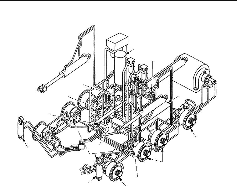
Figure 4. M9 ACE Hydraulic System Major Components.
1. MAIN HYDRAULIC PUMP (Figure 4, Item 1). Fixed displacement pump that pulls hydraulic oil from the
reservoir to perform whatever function is necessary.
2. MAIN ACCUMULATOR (Figure 4, Item 2). Helps keep pressure constant in hydropneumatic suspension
system.
3. SPRUNG/UNSPRUNG VALVE (Figure 4, Item 3). Regulates pressurized fluid flow for whichever mode is
selected.
4. HYDRAULIC RESERVOIR (Figure 4, Item 4). Supplies hydraulic oil through main pump, high-pressure
filters, and DCV to activate hydraulic functions of vehicle.
5. NO. 1 AND NO. 4 ACTUATORS (Figure 4, Item 5). Front: provides vehicle suspension in SPRUNG mode
and allows vehicle to raise and lower in UNSPRUNG mode. Rear: No. 4 is same as front, except they cannot
be raised or lowered.
6. NO. 2 AND NO. 3 ACTUATORS (Figure 4, Item 6). Operate off No. 1 and No. 4 actuators. Interwheel control
valves allow them to follow, rather than lead No. 1 and No. 4 actuators when vehicle is lowered.
03/15/2011Rel(1.8)root(descwp)wpno(G00002)