
TM 5-2350-378-23&P
0006
ALL HYDRAULIC FUNCTIONS INOPERATIVE - Continued
d.
Loosen jam nut (Figure 7, Item 1).
e.
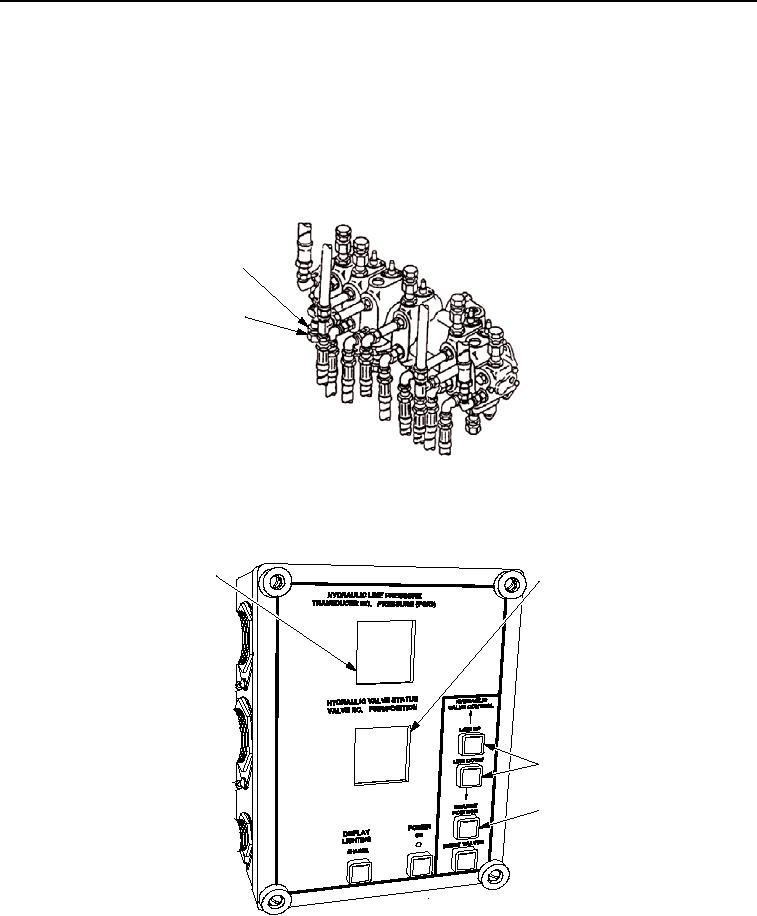
Read transducer T-3 hydraulic pressure on the HDC display
(Figure 8, Item 1), as assistant moves right-hand SUSPENSION CONTROL lever to RAISE and
EJECTOR CONTROL lever to BACK.
f.
Rotate relief valve adjustment (Figure 7, Item 2) clockwise to increase pressure; counterclockwise to
decrease pressure.
1
2
T00414HDC
Figure 7. Main Pump Relief Valve 13R.
g.
When transducer T-3 pressure indicates 3,950-4,050 psi (27,235-27,925 kPa) on the HDC display
(Figure 8, Item 1), tighten jam nut (Figure 7, Item 1).
1
2
3
4
T00412HDC
Figure 8. Hydraulic Diagnostic Center (HDC) Control Box.