TM 5-2350-378-23&P
0034
INSTALLATION - Continued
5.
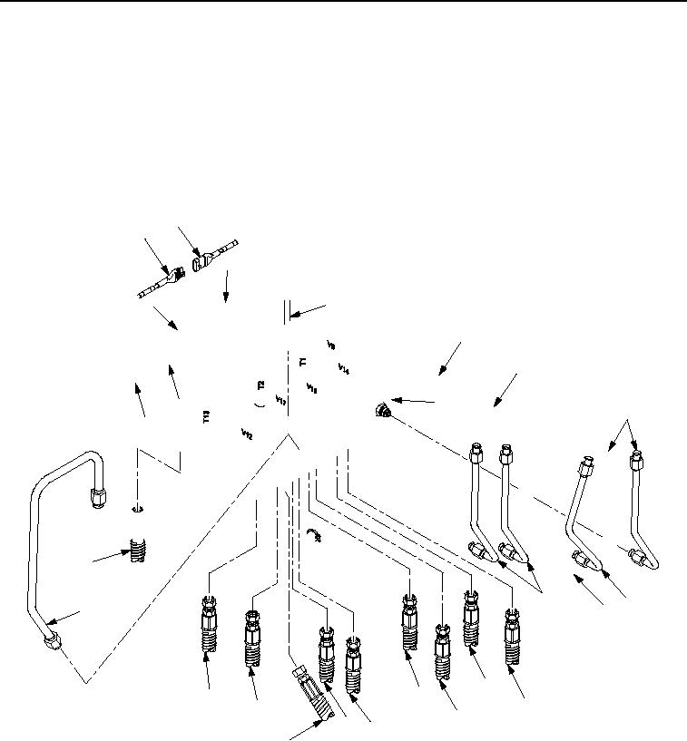
At primary manifold (Figure 4, Item 5) connect wiring harness W2 connectors P2, P31, and P32
(Figure 4, Item 1) to transducers T2, T1, and T13 (Figure 4, Item 2).
6.
At primary manifold (Figure 4, Item 5) connect wiring harness W2 connectors P1, P5, P11, P12, P13, P14,
P15, P16, P17, P19, and P20 (Figure 4, Item 3) to valves V1, V5, V11, V12, V13, V14, V15, V16, V17, V19,
and V20 (Figure 4, Item 4).
7.
Remove caps from adapters and plugs from 17 hydraulic hoses and tubes and connect 17 hydraulic hoses
and tubes (Figure 4, Items 6 through 19) to primary manifold (Figure 4, Item 5).
2
1
2
1
3
4
3
5
2
6
1
19
6
7
18
8
10
12
17
9
16
11
14 13
15
M0039HDC
Figure 4.
Hydraulic Diagnostic Center (HDC) Primary Manifold Assembly and Mounting Bracket Installation.
END OF TASK
03/15/2011Rel(1.8)root(maintwp)wpno(M00011)

