
TM 5-2350-378-23&P
0038
ASSEMBLY
CAUTION
Assembly should be performed in a clean environment and protective dust covers or caps
should be installed on all openings to prevent contamination. Dirt can damage parts and
cause malfunctions.
When securing aft manifold in vise, exercise extreme care not to mar any surfaces or
damage components.
Do not over torque.
1.
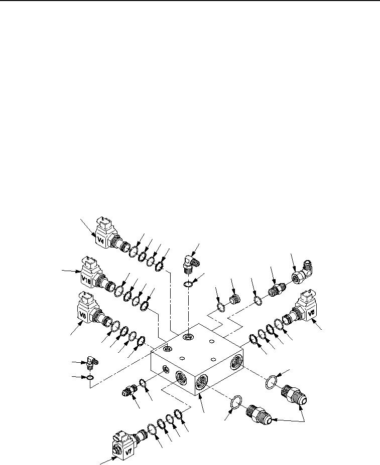
Install five new O-rings (Figure 3, Item 2), five new packing retainers (Figure 3, Item 3), five new O-rings
(Figure 3, Item 4), five new packing retainers (Figure 3, Item 3), one two-way (NC) valve V18
(Figure 3, Item 17), and four two-way (NO) valves V4, V6, V7, and V8 (Figure 3, Item 1) into aft manifold
(Figure 3, Item 13).
2.
Install new O-ring (Figure 3, Item 6), adapter (Figure 3, Item 5), new O-ring (Figure 3, Item 15), adapter
(Figure 3, Item 16), new O-ring (Figure 3, Item 7), plug (Figure 3, Item 8), two new O-rings (Figure 3, Item 11),
two adapters (Figure 3, Item 12), new O-ring (Figure 3, Item 15), adapter (Figure 3, Item 14), new O-ring
(Figure 3, Item 6), adapter (Figure 3, Item 9), and adapter (Figure 3, Item 10) into aft manifold
(Figure 3, Item 13).
1
2
3
5
4
3
10
9
2
17
6
3
6
8
4
7
3
1
1
2
2
3
3
4
4
3
3
16
11
15
15
14
13
11
12
3
4
3
2
1
M0034HDC
Hydraulic Diagnostic Center (HDC) Aft Manifold Assembly.
Figure 3.
03/15/2011Rel(1.8)root(maintwp)wpno(M00010)