 |
|||
|
|
|||
|
Page Title:
Section VII. NUMERICAL PARTS LISTING |
|
||
| ||||||||||
|
|
 TM 9-1425-600-34-5-2
NOTE
For temperatures below -28.9 (29 ) use 3 parts of hydraulic fluid to 1 parts of
C
F
naphtha, specification TT-N95.
b. Check tightness of bolts.
c. Check operation of retractable casters.
d. Operate jack several times to bleed out trapped air. If air is still present, pump jack to full extension, remove
plunger, open the valve (11, figure 3). Lower jack as rapidly as possible without overflowing the pump. With fluid level
at the top of the reservoir, replace the plunger.
40. TEST AFTER OVERHAUL.
a. Install a pressure gage in either pipe plug opening in pump. The gage must be able to indicate 3500 psi.
b. Pump jack up to full extension. Continue operating pump until gage indicates 3182 psi. At this point the relief
valve should bypass fluid to the reservoir and prevent further increase. Raise or lower the setting to obtain correct
pressure. (See paragraph 37).
c. At this pressure, check all points for leaks. The most likely source of leaks are packings damaged during
assembly.
e. Remove gage and install plug.
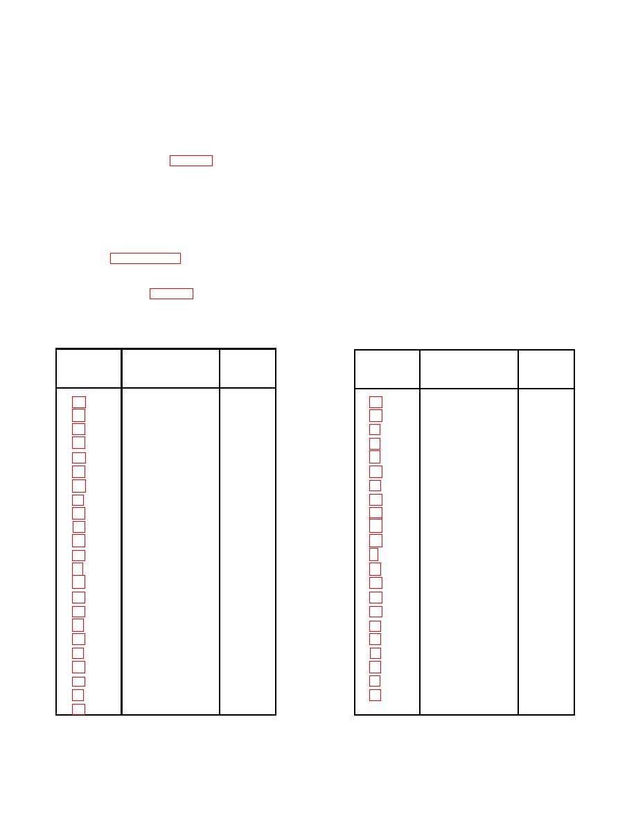
Section VII. NUMERICAL PARTS LISTING
FIG. AND
FIG. AND
INDEX NO.
PART NO.
FMC
INDEX NO.
PART NO.
FMC
AN380-4-6
88044
170-291
22598
AN395-65
88044
190-205
22598
2-18
AN6232-10
88044
5-25
20-118
22598
2-12
AN6232-13
88044
5-23
20-2-23
22598
AN6232-16
88044
2-21
200-32
22598
H5991-2
06004
210-78
22598
MS20392-10-87
96906
220-19
22598
MS20392-4C49
96906
230-23
22598
MS24665-302
96906
5-26
30-171
22598
2-13
MS28782-47
96906
2-29
34
00266
3-10
MS35338-51
96906
347
71447
5-13
MS49005-4
96906
2-4
40-79
22598
4-6
XSC-135
76665
2-25
50-188
22598
2-16
100-23
22598
5-18
59-048-250-100
22598
110-71
22598
2-23
60-236
22598
110-72
22598
65-6-14
22598
110-73
22598
65-6-6
22598
2-10
130-27
22598
70-81
22598
130-128
22598
2-11
70-94
22598
2-31
160-52
22598
79-95
22598
2-32
160-9-03
22598
2-17
80-149
22598
2-26
160-9-13
22598
2-15
90-43
22598
2-27
160-9-25
22598
14
|
|
Privacy Statement - Press Release - Copyright Information. - Contact Us |