 |
|||
|
|
|||
|
Page Title:
Section II: OPERATION AND SERVICE INSTRUCTIONS |
|
||
| ||||||||||
|
|
 T.O. 35A2-2-39-11
T M 55-1730-221-12
OPERATION AND SERVICE INSTRUCTIONS
c. Remove vent assembly (52) and inspect reservoir
f l u i d level to ascertain that fluid is within 1/4 inch of
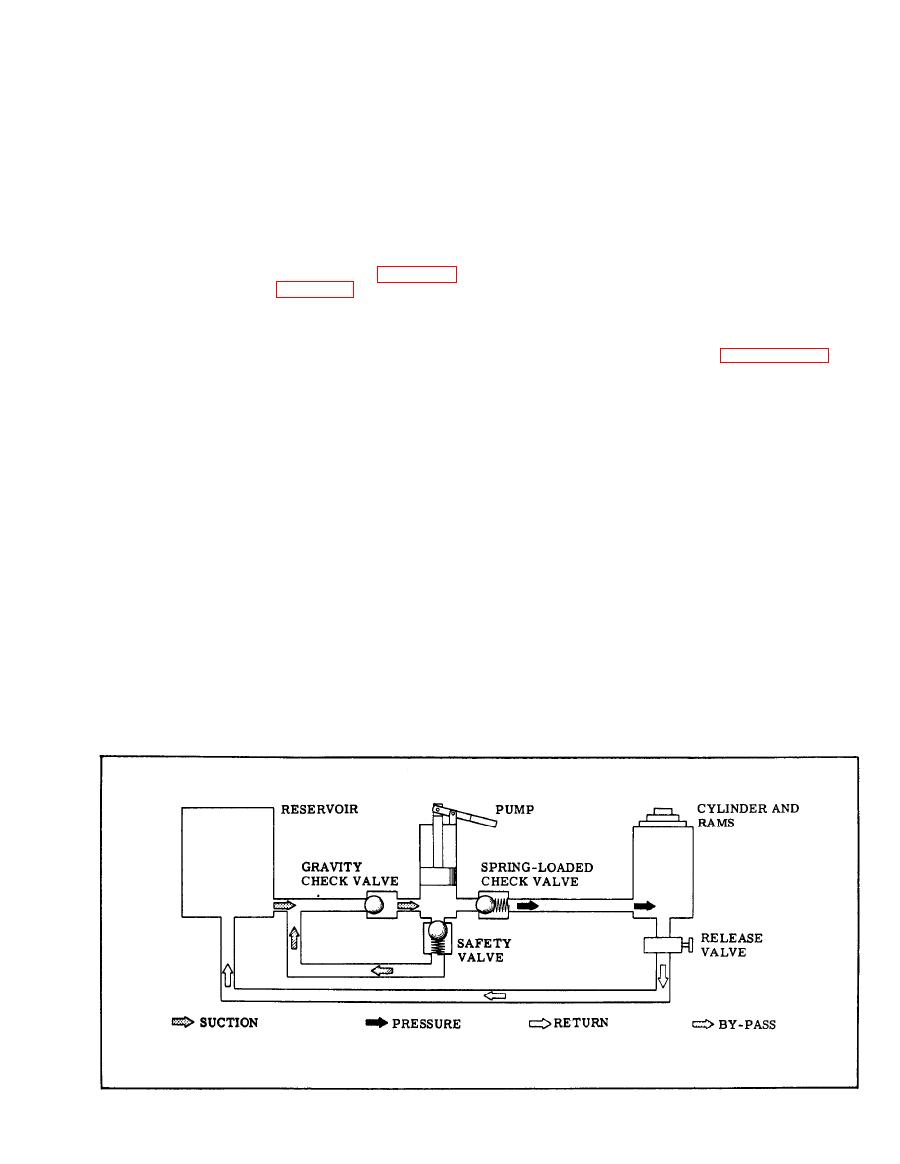
The valve assembly, (14, figure 3-1) is located be-
reservoir filler hole boss.
neath the pump actuating cylinder (12). The valve
assembly contains a gravity check valve, a spring-
loaded check valve and a safety by-pass valve. On
d . If fluid level is low, add sufficient operating fluid
(refer to Leading Particulars, paragraph 1-4, for
the "up" stroke the pump piston (8) draws hydraulic
proper fluid specification) to fill reservoir to correct
fluid from the reservoir, and on the "down" stroke
fluid level.
forces fluid under pressure through the spring-loaded
check valve and into the base assembly (56) cylinder
NOTE
and rams (33, 39, 44). This fluid pressure is retained
by the spring-loaded check valve. Pressure may be
released, and the fluid returned to the resevoir, by
Reservoir shall be filled with fresh, clean
Fluid that has been filtered to remove
fluid.
opening the release valve (25). The safety by-pass
dirt, sand and all other solid matter may be
valve is operative when load to the rams exceeds the
used only in emergency cases. Immediately
m a x i m u m allowable load of 11 tons (10% greater than
after emergency operation, flush jack with
1 0 ton rated load).
clean hydraulic fluid, and fill reservoir to
correct level.
cedure is used to prepare the jack for service:
e . Replace vent assembly (52), allowing vent screw to
remain open approximately two turns. Open release
a . Apply a light film of lubricating oil (Specification
v a l v e (25) one complete turn. Operate jack handle (1)
MIL-L-7870) to outer bearing surfaces of rams. Wipe
f o r ten to twenty pressure strokes to expel all trapped
a w a y excess oil with a clean, lint-free cloth to prevent
dust and grit accumulation on ram surfaces.
air.
f. Close release valve (25). Close screw of vent
b. Open release valve (25) approximately one-half
assembly (52) if jack is to be stored. Vent assembly
turn and manually collapse rams until flush with
screw shall remain open when jack is in service.
cylinder of base assembly (56).
2-1
|
|
Privacy Statement - Press Release - Copyright Information. - Contact Us |
