 |
|||
|
|
|||
|
Page Title:
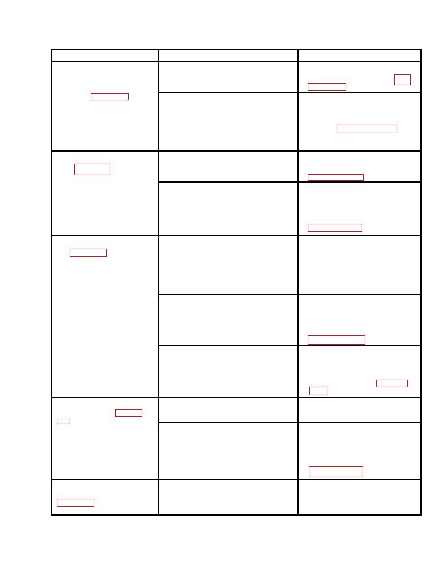
Figure 2-2. Trouble Shooting Chart |
|
||
| ||||||||||
|
|
 T.O. 35A2-2-39-11
TM 55-1730-221-12
TROUBLE
PROBABLE CAUSE
REMEDY
Remove screw (22). Adjust
By-pass valve improperly
R a m s (33, 39, 44) fail to
adjusted.
screw (15) as outlined in para-
l i f t when jack is operated,
o r jack fails to lift rated
l o a d . (See figure 3-1.)
Remove screws (15, 22). Re-
Broken by-pass valve spring
(Continued)
(16).
move, inspect, and if necessary
replace spring (16). Install
s c r e w (15) and adjust as out-
lined in paragraphs 3-11a
through 3-11c. Install screw
(22).
R a m s will not fully elevate.
L o w fluid level.
I n s p e c t and fill to correct fluid
( S e e figure 3-1.)
level if necessary (refer to
Leaking discharge valve.
Remove valve assembly (14).
I n s p e c t ball (20) and ball seat-
i n g surfaces of valve body (21).
R e p l a c e ball (20) if defective;
reseat if necessary (refer to
Remove rams (33, 39, 44).
Rams will not support load.
Oil leaks around rams
(33, 39, 44).
Replace packing retainers (37,
( S e e figure 3-1.)
4 3 , 48), and packings (36, 42,
47). Inspect bearings (35, 41,
4 6 ) and bushing (31) for dam-
a g e d grooving or uneven wear.
Replace defective parts.
Leaking discharge valve.
Remove valve assembly (14).
I n s p e c t ball (20) and ball seat-
i n g surfaces of valve body (21).
R e p l a c e ball (20) if defective.
Reseat if necessary (refer to
Leaking release valve ball
Remove, inspect and if neces-
( 2 7 ) or seat.
sary replace ball (27). Inspect
ball seating surface in base
assembly (56) and reseat if
necessary (refer to paragraph
Incomplete closure of
Tighten release valve (25) se-
Rams rise and fall with
release valve (25).
curely.
each stroke. (See figure
Leaking discharge valve.
Remove valve assembly (14).
I n s p e c t ball (20) and ball seat-
i n g surfaces of valve body (21).
Replace ball if defective. Re-
seat if necessary (refer to
V a c u u m created in res-
Unscrew vent assembly (52)
Pump inoperative or dif-
ficult to operate. (See
e r v o i r due to closed vent
vent screw 2 turns.
assembly (52) vent screw.
2-3
|
|
Privacy Statement - Press Release - Copyright Information. - Contact Us |
