 |
|||
|
|
|||
|
Page Title:
Chapter 6. HYDRAULIC SYSTEM MAINTENANCE INSTRUCTIONS |
|
||
| ||||||||||
|
|
 HYDRAULIC SYSTEM MAINTENANCE INSTRUCTIONS
Section I. RESERVOIR AND SUPPORT
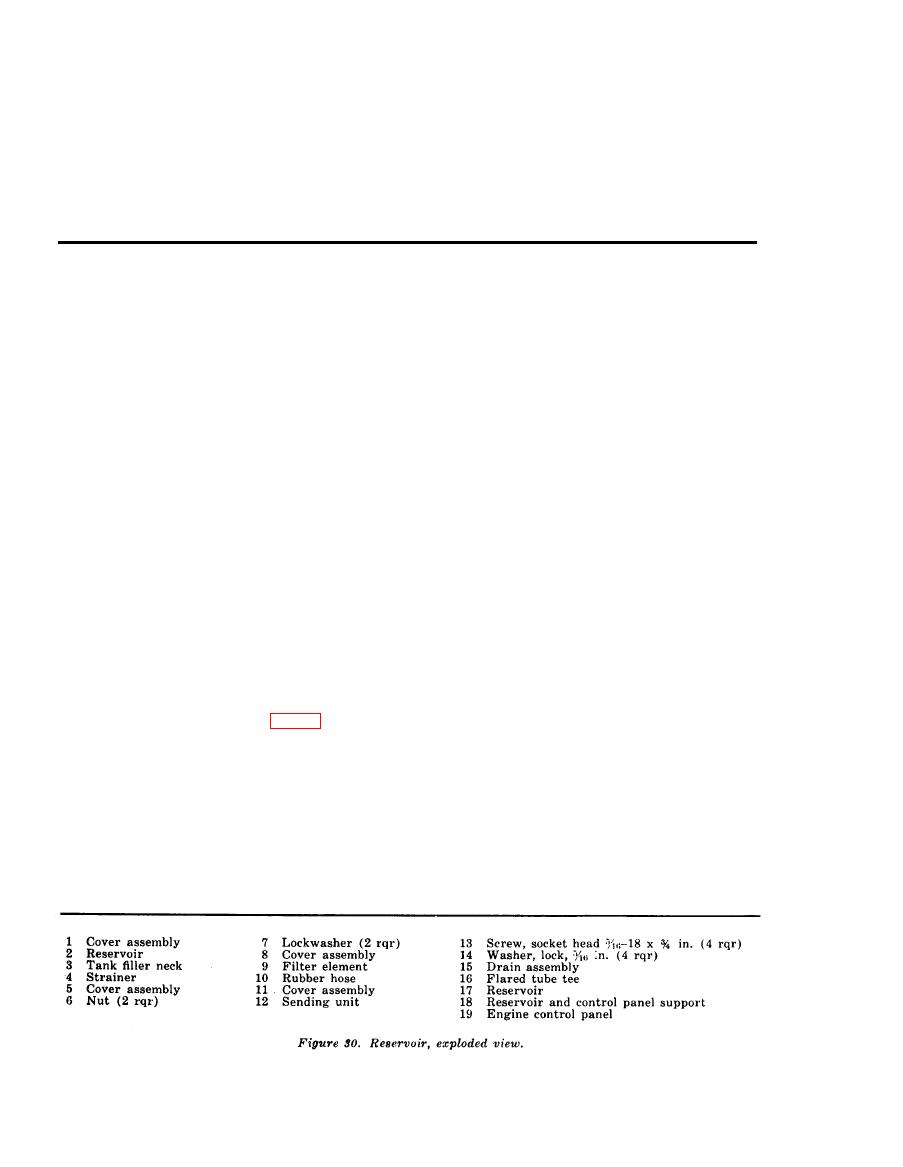
reservoir and remove the cover assem-
139. Reservoir
bly.
a. Removal.
(4) Remove the rubber hose (10) from
(1) Remove the housing assembly (par.
the filter element (9) and the tubing
106).
of the cover assembly.
(2) Remove the drain assembly (15, fig.
(5) Remove the 2 hex nuts (6) and 2 lock-
30) from the reservoir (17) and drain
washers (7) that secure the filter ele-
the hydraulic fluid and discard.
ment in the reservoir cover assembly
(3) Disconnect the relief valve-to-reser-
(8) and remove the filter element.
voir tubing (22, fig, 12), outlet selec-
(6) Remove the eight hex nuts, lockwash-
tor valve-to-reservoir tubing (21), and
ers, and flat washers that secure the
the reservoir-to-shutoff valve tubing
cover assembly (11) and gasket to the
(46) from the flared tube tee (16, fig.
reservoir and remove the cover assem-
30) and from the elbow in the reser-
bly.
voir.
(7) Remove the four screws (13) and lock-
(4) Remove the two straps that secure the
washers (14) that secure the sending
reservoir to the reservoir and control
unit (12) to the cover assembly and
panel support (18) and remove the
remove the sending unit.
reservoir from the support.
c. Cleaning, Inspection, and Repair.
b. Disassembly.
(1) Rinse the inside of the reservoir thor-
(1) Remove the eight hex nuts, lockwash-
oughly with an approved cleaning sol-
ers, and flat washers that secure the
vent. Clean the remaining metal parts
in an approved solvent and dry thor-
cover assembly (1, fig. 30) and the
gasket to the reservoir and remove the
oughly.
cover assembly.
(2) Inspect the reservoir for dents, tears,
(2) Remove the reservoir fill cap (2) from
and damaged and leaking seams. Re-
pair minor leaks by soldering. Replace
the tank filler neck (3). Remove the
strainer (4) from the cover assembly.
a reservoir damaged beyond repair.
(3) Remove the eight hex nuts, lockwash-
(3) I n s p e c t the cover assemblies for
ers, and flat washers that secure the
cracks, breaks, and distortion. Replace
cover assembly (5) and gasket to the
a defective cover assembly.
AGO
5742A
|
|
Privacy Statement - Press Release - Copyright Information. - Contact Us |