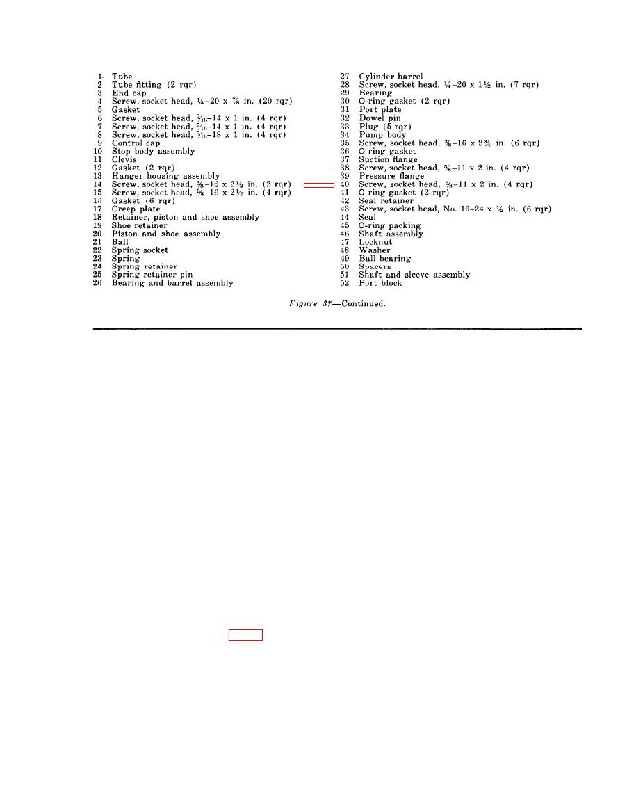
 |
|||
|
|
|||
|
Page Title:
Cleaning, Inspection, and Repair |
|
||
| ||||||||||
|
|
 clevis (39) and install the 2 dowel pins (35 and
a. Clean all parts with an approved cleaning
37).
solvent and dry with a lint free cloth.
d. Place new O-ring packing (23) and O-ring
gasket (24) on the control housing (26). Posi-
stop, and ball support for nicks, burs, scores,
tion the control cap (21) on the housing and
and distortion. Remove minor abrasions. Re-
secure with the two screws (22). Insert the pis-
place a damaged or defective part.
ton (25) in the housing.
c. inspect the control cap, control housing,
e. Install a new preformed packing (20) and
stop body, and clevis for cracks, breaks, distor-
the retaining ring (18) on the control sleeve
tion, and damaged threads. Replace a defective
(19). Insert the control piston (17) in the con-
part.
trol sleeve and install the sleeve with attached
d. Inspect the springs for cracks, distortion,
parts in the control cap.
and for lack of tension. Replace a defective
f. Insert the ball (14), ball support (13),
spring.
spring (12) and seal piston (11) in the adjust-
ment housing (15) and install the housing and
ments and races. Replace a defective bearing.
a new preformed packing (16) in the control
f. Inspect all attaching hardware for distor-
cap.
tion and damaged threads and replace if defec-
g. Install a new preformed packing (10) and
tive.
the lockwasher (9) in the adjustment housing.
205. Reassembly
h. Insert the spring retainer (8), spring (7),
and the control piston (6) in the control cap.
(32) and install the roll pin (30). Place the
i. Install a new O-ring packing (4) and re-
spring (33) on the stop and screw the stop into
taining ring (3) on the control sleeve (5) and
the stop body (34).
slide the sleeve into the control cap.
b. Install the O-ring packing (28) on the
j. Install a new O-ring packing (2) and the
tongue (29) and slide the tongue into the stop
stop spool (1) in the control cap.
body. Install the nut (27) on the stop body.
AGO 5742A
|
|
Privacy Statement - Press Release - Copyright Information. - Contact Us |