 |
|||
|
|
|||
|
Page Title:
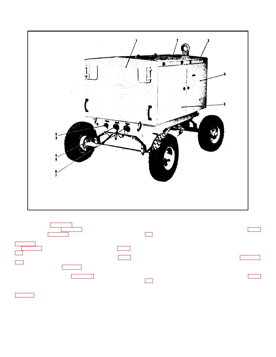
Figure 1-2. Test Stand, Right Rear View |
|
||
| ||||||||||
|
|
 TM 55-4920-335-14
1.
Rear Access Panel
6.
Hose Connections
2.
Access Door
7.
1" Suction Port
3.
Access Door
8.
3/4" Outlet Port
4.
Access Door
9.
1/2" Outlet Port
5.
Access Door
Figure 1-2. Test Stand, Right Rear View
compartment (12, figure 1-3) for storage of handbook and
incorporating tie rods and king pins, is used to provide positive
engine crank. Door (4, figure 1-1) permits access to top of
steering. Rear wheels are equipped with hand lever (11, figure
engine. Door (6, figure 1-1) permits access to control panel,
high pressure pump controls, and low pressure filter. Door (2,
Stand in fixed position during testing operations. The trailer
rolls on four steel wheels equipped with 6.00 x 9 inch, 6 ply
(3, figure 1-2) permits access to top of engine. Door (4, figure
pneumatic tires. Provisions are made for attaching lifting or
tiedown rings to the trailer frame. Bulkhead fittings are
voltage regulator, and fuel fill neck of fuel tank. Door (5, figure
installed in the rear frame for hose connections (6, figure 1-2)
for testing operations.
Each hose connection fitting is
removable front panel (2, figure 1-1) permits access to the front
equipped with a protective cap.
of the engine and contains a hole for insertion of engine crank.
A removable rear panel (1, figure 1-2) permits access to
1-10. GASOLINE ENGINE. The gasoline engine (1, figure
components at rear of unit Including the high pressure filter.
from either side, top, or front of the housing. The engine is a
1-9. RUNNING GEAR AND FRAME. The running gear (7,
four cylinder, four cycle, V type, air cooled unit. Horsepower
varies with rpm ; ranging from 24.5 at 1400 rpm to 36.0 hp at
vehicle towing at speeds up to 20 mph. Two leaf springs (10)
2400 rpm.
are provided to ensure good riding qualities without materially
increasing frame height. A knuckle type steering apparatus,
1-4
|
|
Privacy Statement - Press Release - Copyright Information. - Contact Us |
