 |
|||
|
|
|||
|
|
|||
| ||||||||||
|
|
 TM 55-4920-335-14
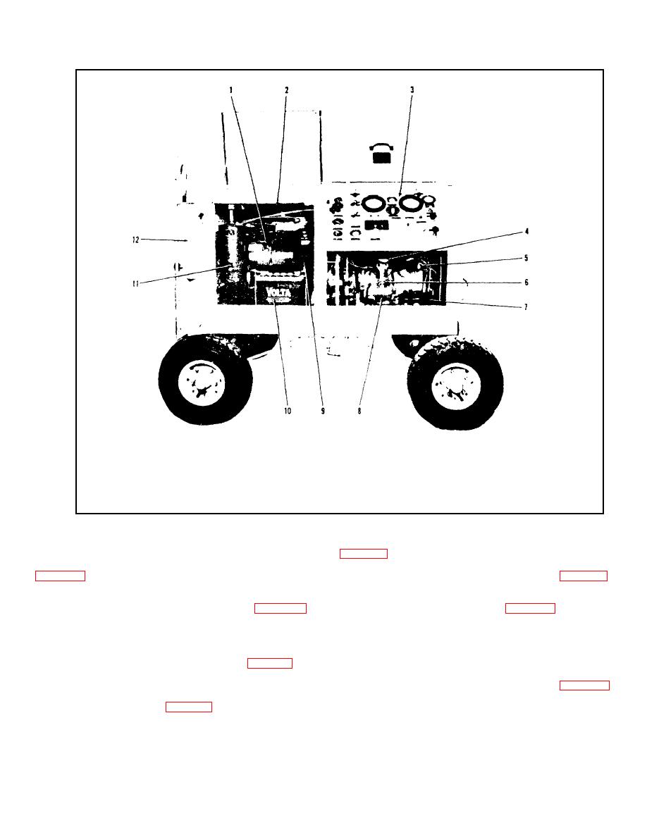
1.
Gasoline Engine
7.
Low Pressure Filter
2.
8.
High Pressure Pump
3.
Control Panel
9.
Engine Oil Filter
4.
Pump Volume Control
10.
Battery
5.
High Pressure Filter
11.
Air Cleaner
6.
Pump Compensator Control
12.
Hand Book Compartment
Figure 1-3. Test Stand - Left Side
Engine speed is held automatically at the selected rpm by a
1-11. HIGH PRESSURE PUMP. The high pressure pump (8,
centrifugal flyball governor which adjusts the throttle to
compensate for changes in engine load. A 12 volt battery (10,
driven by it through a flexible coupling. The pump incorporates
the following features : a fluid volume control (4, figure 1-3)
engine may also be started by a hand crank.
providing regulation of pump delivery from 0 to 10 gpm at
operating pressures ranging from 800 to 5000 psi; an
a. Air Cleaner. The engine air cleaner (11, figure 1-3)
adjustable pressure compensator (6, figure 1-3) which, at a
filters the air entering the carburetor, prolonging the life of the
predetermined pressure, reduces pump delivery to the
engine. The air cleaner is equipped with a pre-cleaner at the
minimum requirement to maintain pressure in the system, and
top.
a compensator shut-off valve which permits isolating the
compensator from the system when adjusting the high
b. Engine Oil Filter. The engine oil filter (9, figure 1-3) is
pressure relief valve.
a disposable cartridge type unit built to MIL-E-11275
specifications.
1-12. CONTROL PANEL. The control panel (3, figure 1-3)
contains all switches, gages, fault indicators, and controls used
c. Muffler. A muffler (2, figure 1-3) is provided at the top
in the operation of the Test Stand.
of the engine for noise and exhaust control.
1-5
|
|
Privacy Statement - Press Release - Copyright Information. - Contact Us |
