 |
|||
|
|
|||
|
|
|||
| ||||||||||
|
|
 TM 55-4920-335-14
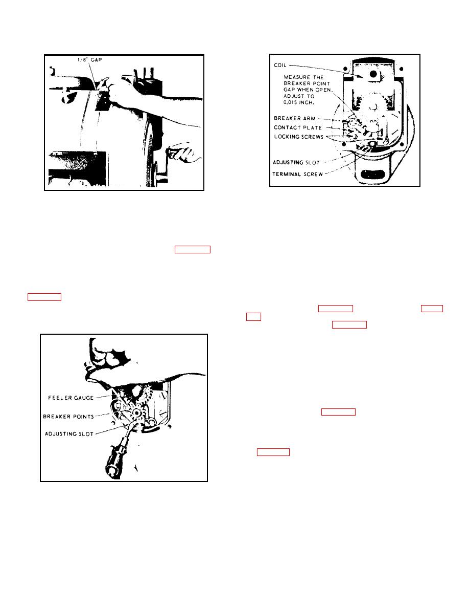
Figure 4-6. Magneto - End View
Figure 4-4. Checking Magneto Ignition Spark
(3) Tighten locking screws and recheck breaker point
b.
Replace points that are badly worn or pitted.
gap to make sure it has not changed.
c. Rotate crankshaft with hand crank (this also rotates
4-14.
ADJUSTING THERMOSWITCH.
An inboard
magneto) until breaker points are wide open. Measure
thermoswitch is installed in the hydraulic manifold and should
opening or gap with a feeler gage as shown in figure 4-5. At
be adjusted so that its contacts open, shutting down the Test
full separation, gap shall be 0.015 inch.
Stand when system hydraulic fluid temperature reaches 71
degrees C (160oF).
Turn adjusting screw in head of
d.
Adjust breaker points as follows:
thermoswitch clockwise to increase temperature setting,
counterclockwise to decrease the temperature setting.
(1) Loosen two locking screws on contact plate
4-15. CLEANING HYDRAULIC RESERVOIR. To clean
(2) Insert end of small screwdriver into adjusting slot
hydraulic reservoir (1, figure 1-4), open access door (2, figure
at bottom of contact plate and open or close contacts by
moving plate until proper gap is obtained.
reservoir shutoff valve (1, figure 3-1) and drain reservoir by
opening drain valve in bottom. Remove top cover plate from
reservoir for access to interior. After cleaning, reassemble and
refill reservoir.
4-16. REPAIR AND REPLACEMENT. Paragraphs 4-17
through 4-19 contain instructions for repair and replacement of
maintenance - significant components for which the
procedures are not obvious.
4-17. GENERATOR REPAIR AND REPLACEMENT. Repair
or replace generator (2, figure 1-4) as follows:
a.
Removal.
(1) Disconnect electrical leads from voltage regulator
(3, figure 1-4).
(2) Remove hardware attaching generator to slotted
bracket and remove fan belt from generator pulley.
(3) Remove mounting hardware securing generator
to rear mounting bracket and remove generator from Test
Stand.
Figure 4-5. Measuring Magneto Point Gap
4-6
|
|
Privacy Statement - Press Release - Copyright Information. - Contact Us |
