 |
|||
|
|
|||
|
Page Title:
GASOLINE ENGINE REPAIR AND REPLACEMENT. |
|
||
| ||||||||||
|
|
 TM 55-4920-335-14
(2) Attach starting motor to support bracket with one
(4) Remove four cap screws, lock washers, nuts,
screw and lock washer at rear of motor.
and eight flat washers mounting engine to frame. Use a
(3) Connect electrical lead to motor.
suitable hoist and carefully remove engine from Test Stand.
4-19. GASOLINE ENGINE REPAIR AND REPLACEMENT.
b.
Disassembly.
Remove and repair gasoline engine (1, figure 1-3) as follows:
(1) Remove starting motor and magneto. Remove
a.
Removal.
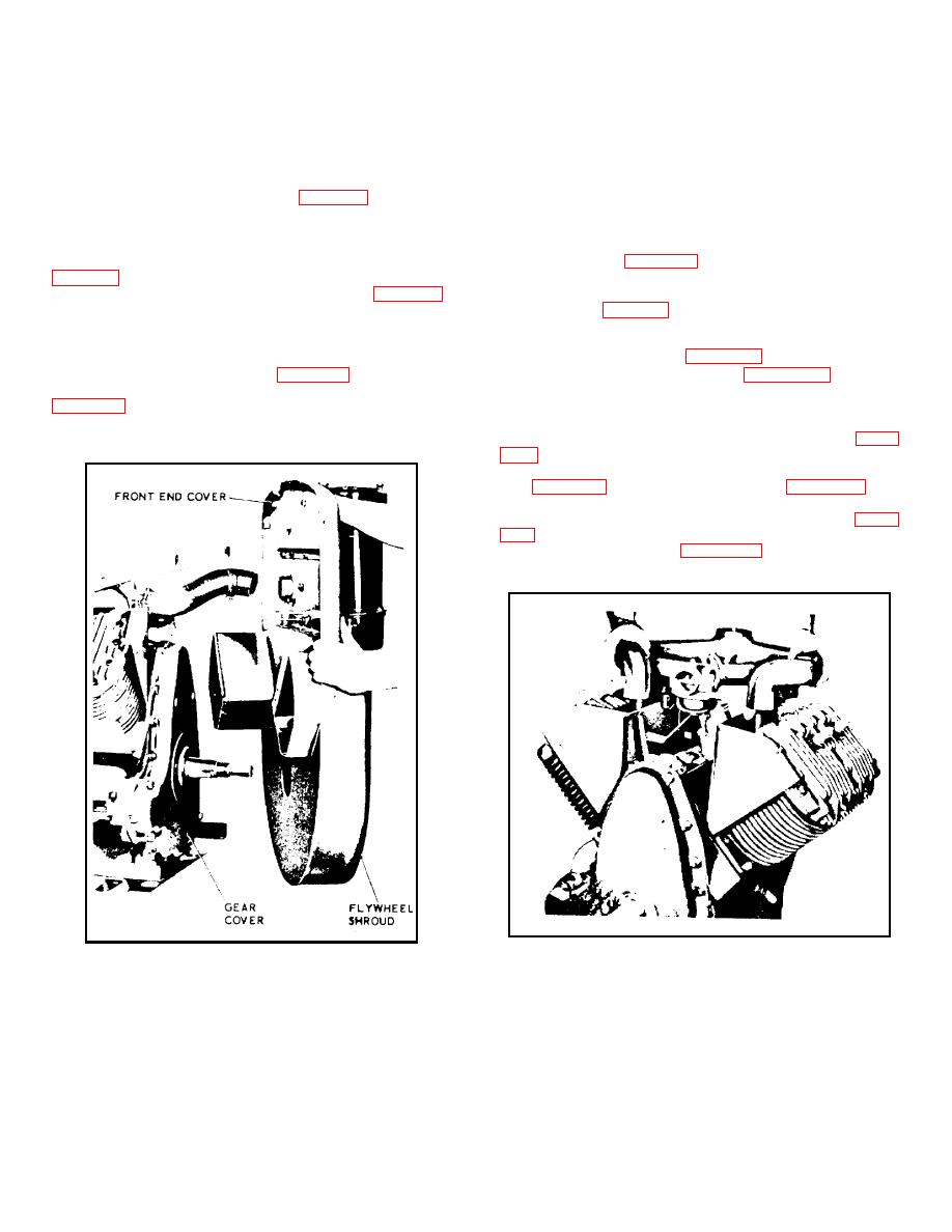
cylinder head covers and screws mounting flywheel shroud to
lower cylinder shrouds and heat deflectors. Remove front end
(1) Remove Test Stand housing. Remove muffler (2,
panel as shown in figure 4-7. Remove balance of shrouding.
Drain crankcase oil.
(2) Disconnect oil lines from oil filter (9, figure 1-3).
(2) Remove carburetor and manifold as an
Disconnect fuel line from fuel pump. Disconnect choke and
assembly. See figure 4-8. Remove cylinder heads.
throttle cables from engine. Disconnect electrical lead to
(3) Disconnect governor linkage and remove
starting motor. Disconnect electrical leads from control panel
governor assembly. Remove gear cover screws and drive out
indicators and switches at engine.
two dowel pins as shown in figure 4-9. Remove gear cover
(3) Loosen generator (2, figure 1-4) in slot of front
exposing timing gears as shown in figure 4-10. Remove
bracket and remove fan belt. Support high pressure pump (8,
camshaft thrust plunger and spring to prevent loss.
(4) Remove setscrew on magneto side of crankcase
pump mount to rear of engine. Disconnect flexible coupling
which locks idler shaft in position. Remove idler gear
between pump shaft and engine crankshaft.
assembly and idler shaft using a gear puller as shown in figure
(5) Invert engine and remove oil pan and supports.
See figure 4-12. Take out slotted pipe plug (figure 4-13) and
then, use a 5/32 inch allen wrench to remove oil pump lock
screw. Remove lock nut holding oil pump driving gear (figure
through gear as shown in figure 4-14. Withdraw oil pump
toward center of crankcase.
Figure 4-8. Removing Carburetor and Manifold
Figure 4-7. Removing Flywheel Shroud
4-8
|
|
Privacy Statement - Press Release - Copyright Information. - Contact Us |
