 |
|||
|
|
|||
|
|
|||
| ||||||||||
|
|
 TM 55-4920-335-14
(8) Install gear cover (figure 4-9) and tighten gear
cover cap screws 14 to 18 foot pounds torque. Install governor
FULL
NO
HOLE
and governor housing.
LOAD
LOAD
No
(9) Remove all carbon and lead deposits from
R.P.
R.P.1.
cylinder heads. Use a new cylinder head gasket at assembly.
1400
1550
4
Apply a mixture of graphite and oil to cylinder head screws to
1500
1650
5
prevent them from rusting tight against cylinder block. Tighten
cylinder head screws 25 to 32 foot pounds torque and, after
1600
1725
5
complete assembly and engine is run-in, retorque head
1700
1850
6
screws.
(10) Install carburetor and manifold assembly figure
1800
1950
7
1900
2050
8
torque. Overtightening may cause flanges to break.
(11) Install magneto and starting motor.
Install
2000
2125
8
shrouding (figure 4-7).
2100
2250
9
2200
2350
10
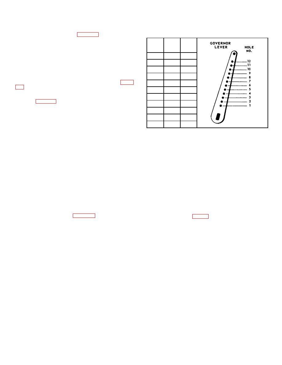
e. Governor Adjustment.
The control rod between
governor and carburetor must be adjusted to proper length.
2300
2425
10
With engine at rest, the governor spring will hold flyweights in,
2400
2550
11
and control rod must be of such length as to hold carburetor
throttle wide open at that point.
The accuracy of this
Figure 4-23. Governor Lever Chart
adjustment can be tested as follows:
f. Installation.
(1) Disconnect control rod ball joint from governor
lever and push rod assembly toward carburetor as far as it will
(1) Use a suitable hoist and carefully position engine
go. This will open throttle wide.
onto frame of Test Stand. Secure engine to frame with four
(2) Move governor lever as far as possible in same
cap screws, lock washers, nuts, and eight flat washers.
direction as control rod. Holding both parts in this position,
(2) Connect flexible coupling between high pressure
screw ball joint onto control rod until right angle stud on ball
pump shaft and engine crankshaft. Attach pump mount to rear
joint fitting will register with hole in lever then, screw fitting in
of engine using four screws and lock washers. Position fan
two more turns.
belt over engine pulley and generator pulley and tighten
(3) Insert ball joint stud into hole in governor lever,
generator in slotted bracket while putting tension on belt.
assemble and tighten lock nuts. With governor lever pushed
(3) Connect electrical leads to engine and starting
toward carburetor as far as it will go, there should be 1/16 inch
motor. Connect throttle and choke cables. Connect fuel line to
clearance between throttle lever and stop pin on carburetor.
fuel pump. Connect oil lines to oil filter. Install muffler. Refill
(4) The governor lever is furnished with 12 holes for
crankcase with oil.
attaching governor spring. It is important that spring is hooked
into proper hole to suit speed at which engine is operated.
4-20. LUBRICATION. Table V is a lubrication chart indicating
Insert spring in hole number 7, figure 4-23.
lubricant specification, time of application, quantity and point of
lubrication.
4-13
|
|
Privacy Statement - Press Release - Copyright Information. - Contact Us |
