 |
|||
|
|
|||
|
|
|||
| ||||||||||
|
|
 TM 55-4920-405-13&P
4-3. TROUBLE ANALYSIS.
Red leadwire to black leadwire -
no
continuity
a . Electrical System. Locate defective parts
Black leadwire to red leadwire -
no
of the electrical system as follows:
continuity
Black leadwire to engine ground
- no
(1)
Battery. Check the specific gravity of the
continuity
battery with a hydrometer. The specific
Engine ground to black leadwire
-
gravity of each cell should be between
continuity
1.285 and 1.300. If it is below 1.285,
charge the battery. If the battery fails to
If any of these readings is not obtained,
take a charge, replace the battery.
the voltage regulator is bad.
(2)
(5)
Ignition Wire Assembly. Check for con-
R e c t i f i e r . With the rectifier plug discon-
tinuity from end to end of each ignition
nected from the rest of the electrical sys-
tem, check ohmmeter readings between
wire with an ohmmeter. You should get a
continuity (less than 1 ohm) indication for
the following points:
each wire. If you do not, the ignition wire
is defective.
White leadwire to black 1
leadwire - no
(3)
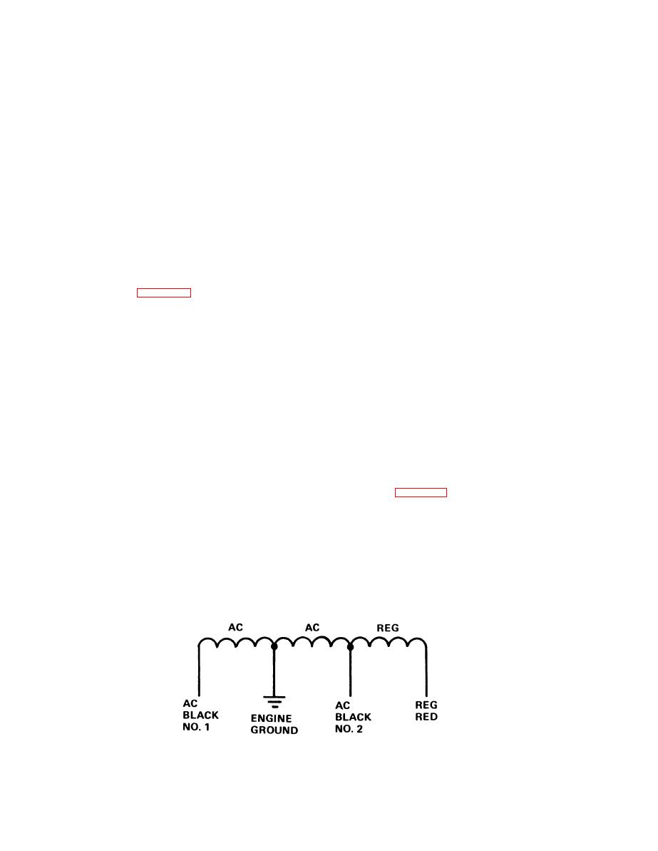
Alternator. The alternator is made up of
continuity
two major parts: a rotor and a stator.
Black 1 leadwire to white
leadwire -
Check to see that each separate cut be-
continuity
tween the rotor electromagnets is free of
White leadwire to black 2
leadwire - no
dirt. See figure 4-2 for the schematic
continuity
diagram of the stator. Wire numbers
Black 2 leadwire to white
leadwire -
shown on the schematic diagram are for
continuity
convenience in referencing only. These
numbers do not appear on the wires.
NOTE
Squeeze the outer ends of the plug recept-
Continuity should be in one direction only.
acles on the alternator leadwires, and
pull the plugs apart. Then, check the
If you do not get these readings, the recti-
resistance of the stator windings with an
fier is bad.
ohmmeter. The approximate resistance
(6)
readings are:
Starter Switch, Solenoid, and Motor. If
you think that the starter circuits may be
Black
1
to
black 2 - 0.40 ohm
bad, use a DC voltmeter to trace voltage
Black
1
to
engine ground - 0.20 ohm
in these circuits. Set the IGNITION
Black
2
to
engine ground - 0.20 ohm
SWITCH to ON. Hold in the STARTER
switch, and check for 12 volts DC (mea-
Black
1
to
red - 3.20 ohms
sured to ground) at the input and output
Black
2
to
red - 2.80 ohms.
terminals of the STARTER solenoid, and
If you get an open indication between any
at the input terminal of the starter motor.
of these measurement points, the alter-
(See figure 4-3.) You should get a 12 volt
reading at each of these points. If you do
nator is bad.
(4)
Voltage Regulator. To test the voltage
and the starter motor does not turn over,
regulator, use an ohmmeter and check to
the starter motor is bad. If you get a 12
see that you get the following ohmmeter
volt reading at the input of the STARTER
solenoid, but not at the output terminal of
readings between the listed points:
the same part, that part is bad.
Electrical Wiring and Cables. To check
Red leadwire to engine ground - no
(7)
the electrical wiring and cables, discon-
continuity
Engine ground to red leadwire - no
nect the battery cables from the battery
terminals. Then, check each wire and
continuity.
Figure 4-2. Alternator Stator, Schematic Diagram
4-8
|
|
Privacy Statement - Press Release - Copyright Information. - Contact Us |
