 |
|||
|
|
|||
|
Page Title:
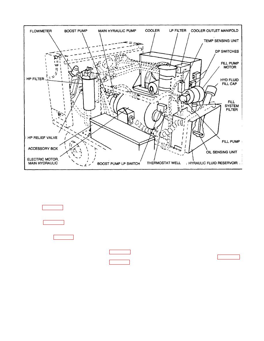
FIGURE 1-2. INTERNAL COMPONENTS ASSEMBLY |
|
||
| ||||||||||
|
|
 TM 55-4920-442-13&P
FIGURE 1-2. INTERNAL COMPONENTS ASSEMBLY
Housing. Hinged doors on the sides of the cabinet permit access to all internal components. A hinged instrument panel
cover protects the controls when the test stand is not in use. The accessory box is located near the center of the unit on
the right side (figure 1-2).
Electric motor. Power for the test stand is supplied by a 60 horsepower, 230/460 volt, 3 phase, 60 hertz, 3535 RPM
electric motor (figure 1-2).
Electrical components panel. The circuit breaker and starter for the electric pump motor is located in the electrical
components panel (figure 1-1) at the front of the unit as are the circuit breakers and starters for the fill pump and cooling
fan.
Main hydraulic pump. The main hydraulic pump (figure 1-2) supplies fluid at high pressure for testing of a high pressure
pump section and integral boost pump section. The pump contains a manual compensator control (figure 1-1) for
varying the output pressure and volume control (figure 1-1) to regulate the output volume by changing the stroke length
of the pumping pistons. Change in piston stroke length is controlled by system pressure so that when the pump is
operating at a pressure less than the maximum setting of the compensator
1-4
|
|
Privacy Statement - Press Release - Copyright Information. - Contact Us |
