|
| |
TM9-6115-667-13&P
SERVICE INSTRUCTIONS
Note: For orientation of piece parts in the following
procedures, refer to the parts location diagram contained
in the PARTS LIST section of this manual.
RECEPTACLE PANEL
REMOVAL AND
REPLACEMENT
REMOVAL
1.
Clean the exterior of the hydraulic motor
generator and place on a clean work surface.
2.
Remove the four 5/16-24 x 1/2 inch/1.27 cm long
machine screws (21, figure 2) securing the receptacle
panel assembly (2) to the receptacle box (5).
3.
Locate the wire harness connected between the
stator (13) and the receptacle panel (2). In this wire
harness are a green, white, and black wire.
Tag and disconnect each of these from the receptacles
(19 & 20) on the receptacle panel (2).
4.
The receptacle panel assembly (2) can now be
laid aside or its components individually inspected and
serviced as required.
REPLACEMENT
1.
Connect the green, white, and black wires in the
wire harness to the appropriate terminals. Refer to the
wiring diagram for the correct connections.
2.
Install
the
receptacle
panel
(2)
onto
the
receptacle box (5) and secure with four 5/16-24 x 1/2
inch long phillips head machine screws (21).
ROTOR REMOVAL
AND REPLACEMENT
REMOVAL
1.
Remove nuts (10), washers (9), and feet (35)
which secure the frame weldment (36) to the hydraulic
motor generator. Remove the hydraulic motor generator
from the frame weldment (36).
2.
Perform steps 1 through 4 of the RECEPTACLE
PANEL REMOVAL procedure.
3.
Locate the capacitor (18) in the receptacle box
(5), tag and disconnect the two red wires connected to it.
4.
Remove the four 1/4-20 x 91/2 inchl32 cm long
stator bolts (4) securing the stator (13) between the
receptacle box (5) and the outboard bearing bracket
assembly (7) and the inboard engine end adapter (26).
Set the receptacle box (5) aside.
5. Using a soft-faced mallet, carefully and lightly tap
around the outboard bearing bracket assembly (7) from
the inboard side until it is free of the stator (13).
6. Lift the stator (13) free of the inboard engine end
adapter (26) and lay it aside.
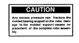
7. Remove the rotor assembly (24) from the Hyrevz
motor (31) drive shaft by loosening the rotor attaching
capscrew (22) using a typical thinwall 1/2-inch end
wrench until the "C” washer (23) drops out. Lift the rotor
assembly (24) up and away from the inboard engine end
adapter (26). It may be necessary to loosen the
capscrew (22) against the rotor assembly to force the
rotor assembly off the Hyrevz motor drive shaft.
8
|


