
TM 5-2350-378-23&P
0015
HYDRAULIC OIL OVERHEATS - Continued
STEP
36.
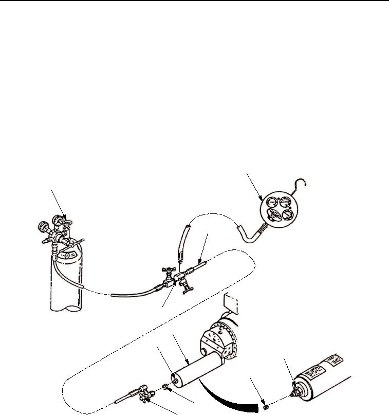
Remove all test equipment and connect hoses.
a.
Tighten nut (Figure 48, Item 4) on actuator accumulator (Figure 48, Item 7).
b.
Close nitrogen tank valve (Figure 48, Item 1) to ease pressure.
c.
Open bleed valve (Figure 48, Item 8), bleed line pressure to 0 psi.
d.
Remove adapter valve (Figure 48, Item 6) from actuator accumulator (Figure 48, Item 7).
e.
Remove pressure measuring device (Figure 48, Item 3) from bleed valve (Figure 48, Item 8) on charging
harness (Figure 48, Item 2).
f.
Install valve cap (Figure 48, Item 5) on actuator accumulator (Figure 48, Item 7).
3
1
2
8
7
4
4
5
5
6
T01367HDC
Figure 48. Actuator Accumulator Pressure Test.
CONDITION/INDICATION
Is all test equipment removed?
DECISION
YES - Verify with operator.
NO - Repeat Step (36).
03/15/2011Rel(1.8)root(tswp)wpno(T00013)