
TM 5-2350-378-23&P
0020
WINCH WILL NOT PULL RATED LOAD - Continued
STEP
4.
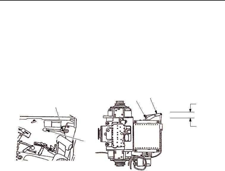
Perform winch shift linkage adjustment check.
a.
Set control lever (Figure 9, Item 2) in NEUTRAL detent (Figure 9, Item 1).
b.
Move lever (Figure 9, Item 4) from side to side and measure for proper shift rod (Figure 9, Item 3)
NEUTRAL position.
c.
Shift rod (Figure 9, Item 3) must move at least 0.10 in. (2.54 mm) in either direction without engaging
LOW or HIGH gear.
d.
Total NEUTRAL zone travel is 0.34 in. (8.64 mm).
e.
Go to Step (5) if shift rod (Figure 9, Item 3) NEUTRAL travel is not within limits.
4
3
0.34 IN.
1
(8.64 MM)
HIGH
NEUTRAL
LOW
2
T01814HDC
Figure 9.
Winch Shift Linkage.
CONDITION/INDICATION
Does linkage fully engage high and low positions?
DECISION
YES - Replace winch motor (TM 5-2350-262-20).
NO - Go to Step (5).
STEP
5.
Adjust winch HIGH/LOW linkage.
NOTE
Ensure control lever is in NEUTRAL detent.
Control lever must move 0.10 in. (2.54 mm) in either direction without engaging
winch. Total NEUTRAL travel zone is 0.34 in. (8.64 mm).
a.
Remove cotter pin (Figure 10, Item 4) and clevis pin (Figure 10, Item 1) from clevis (Figure 10, Item 2)
and control lever (Figure 10, Item 5).
b.
Discard cotter pin (Figure 10, Item 4).
03/15/2011Rel(1.8)root(tswp)wpno(T00018)