
TM 5-2350-378-23&P
0032
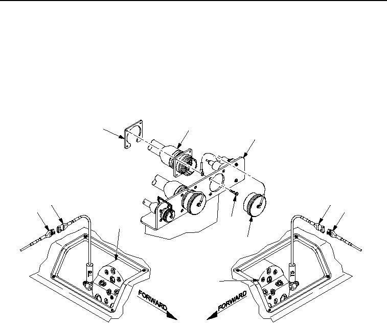
INSTALLATION - Continued
7.
Connect wiring harness W3 connector P31 (Figure 6, Item 10) to transducer T6 (Figure 6, Item 11) at forward
left actuator #1 (Figure 6, Item 9).
8.
Connect wiring harness W3 connector P5 (Figure 6, Item 7) to transducer T5 (Figure 6, Item 6) at forward right
actuator #1 (Figure 6, Item 8).
9.
Install wiring harness W3 connector J1 (Figure 6, Item 2) to HDC disconnect bracket (Figure 6, Item 3) with
nutplate (Figure 6, Item 1) and four screws (Figure 6, Item 4). Attach dust cap (Figure 6, Item 5) to connector
J1.
2
1
3
11
6
10
7
4
9
5
8
LEFT ACTUATOR
RIGHT ACTUATOR
ACCESS AREA
ACCESS AREA
M0023HDC
Figure 6.
Wiring Harness W3 to Disconnect Bracket and Actuator Area Installation.
END OF TASK
FOLLOW-ON MAINTENANCE
1.
Connect negative battery cables (TM 5-2350-262-20).
2.
Install hull access plates (TM 5-2350-262-20).
3.
Remove vehicle from jack stands and lower hull (TM 5-2350-262-20).
4.
Return ejector to stowed position (TM 5-2350-262-10).
5.
Return apron to stowed position (TM 5-2350-262-10).
END OF TASK
END OF WORK PACKAGE
03/15/2011Rel(1.8)root(maintwp)wpno(M00007)