
TM 5-2350-378-23&P
0033
REMOVAL
NOTE
All transducers are removed and replaced in the same manner. This task covers the
removal and replacement of only one transducer.
Refer to Table 1. Hydraulic Diagnostic Center (HDC) Pressure Transducer Locations for
the location of each pressure transducer.
Tag electrical connector and hydraulic hose/tube to assist in installation. Plug fitting that
transducer is removed from to prevent leakage.
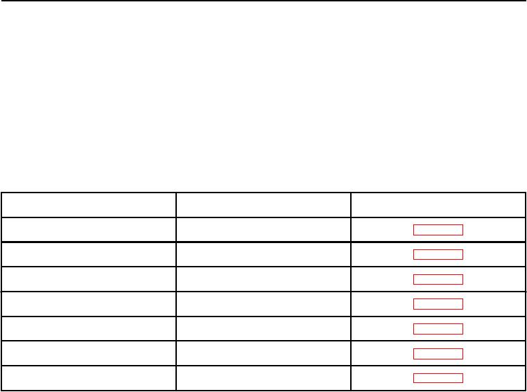
Table 1.
Hydraulic Diagnostic Center (HDC) Pressure Transducer Locations.
Transducer
Location
WP #
T3, T4, T12
Main hydraulic filter area
T5, T8
Right actuator access area
T6, T9
Left actuator access area
T7
Left main manifold
T1, T2, T13
Primary manifold
T10
Left forward manifold
T11
Main hydraulic filter area
1.
If wiring harness and connector are connected, disconnect transducer connector (Figure 1, Item 2) from wiring
harness connector (Figure 1, Item 1).
2.
Remove transducer (Figure 1, Item 4) and O-ring (Figure 1, Item 3) from component. Discard O-ring.
END OF TASK
INSTALLATION
1.
Install new O-ring (Figure 1, Item 3) and transducer (Figure 1, Items 2 and 4) on component.
2.
Connect transducer connector (Figure 1, Item 2) to wiring harness connector (Figure 1, Item 1).
03/15/2011Rel(1.8)root(maintwp)wpno(M00014)