 |
|||
|
|
|||
|
Page Title:
Figure 2. Aircraft hydraulic test stand, three-quarter, left rear view. |
|
||
| ||||||||||
|
|
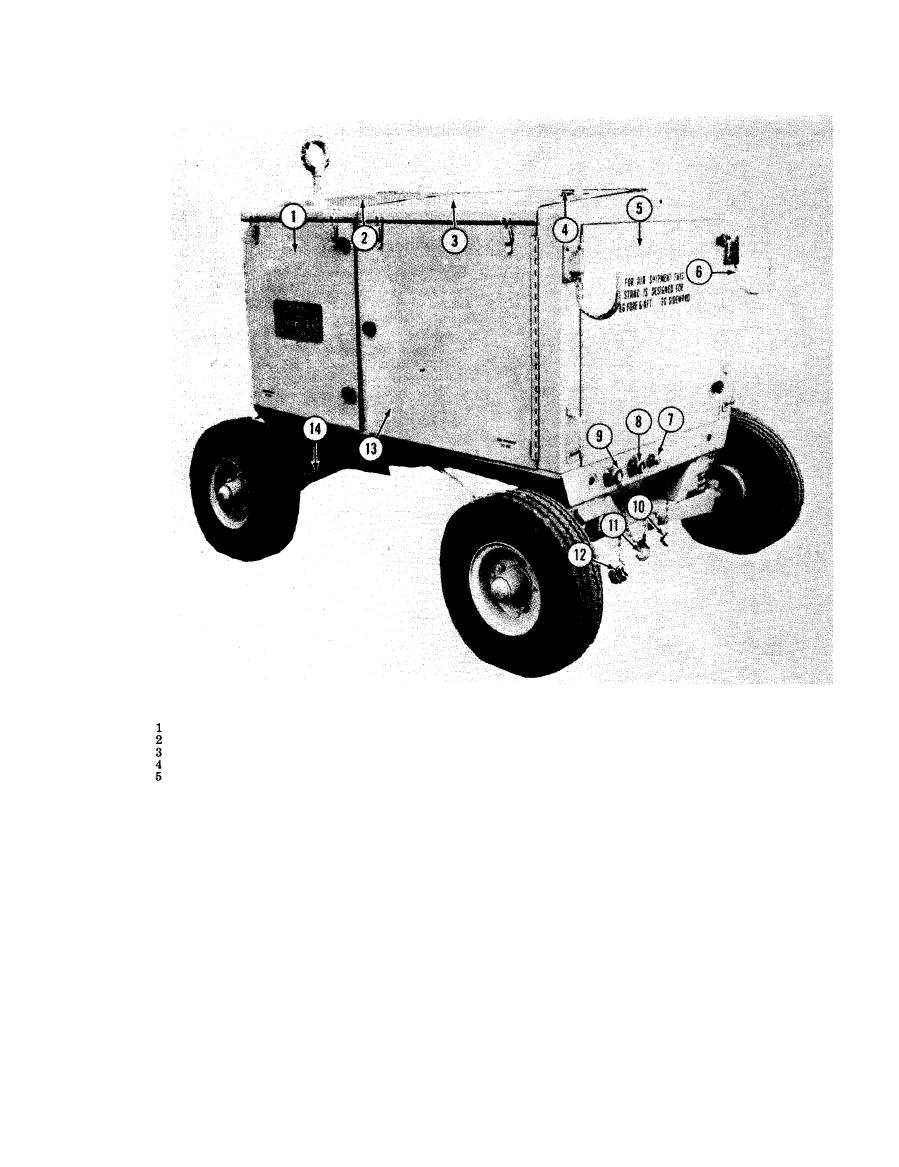 Dust protective cap, in.
11
6
Hose support hook
Left front door assembly
Dust protective cap, 1 in.
12
7
Coupling half, in.
Front top door assembly
13
Left rear door assembly
8
Coupling half, in.
Rear top door assembly
9
14
Tie rod
Coupling half, 1 in.
Reservoir fill cap
10
Dust protective cap, in.
Rear door assembly
volume control providing regulation of pump
door assembly (3). A reservoir shutoff valve
delivery from 0 to 10 gpm (gallons per min-
is provided for isolating the test stand reservoir
ute ) at operating pressures ranging from 200
from the hydraulic system when using fluid
from the aircraft reservoir or when the test
to 5000 psi (pounds per square inch) output,
stand is utilized to drain the hydraulic system
and to 100 psi maximum input: an adjustable
of the aircraft. Door assemblies (3 and 13)
compensating control mounted on the control
provide access to the reservoir for service and
panel, which at the predetermined pressure,
maintenance.
reduces pump delivery to the minimum require-
e. Hydraulic Pump. The hydraulic pump
ment to maintain pressure in the system.
incorporates the following features: a pump
5
AGO 5742A
|
|
Privacy Statement - Press Release - Copyright Information. - Contact Us |
