 |
|||
|
|
|||
|
Page Title:
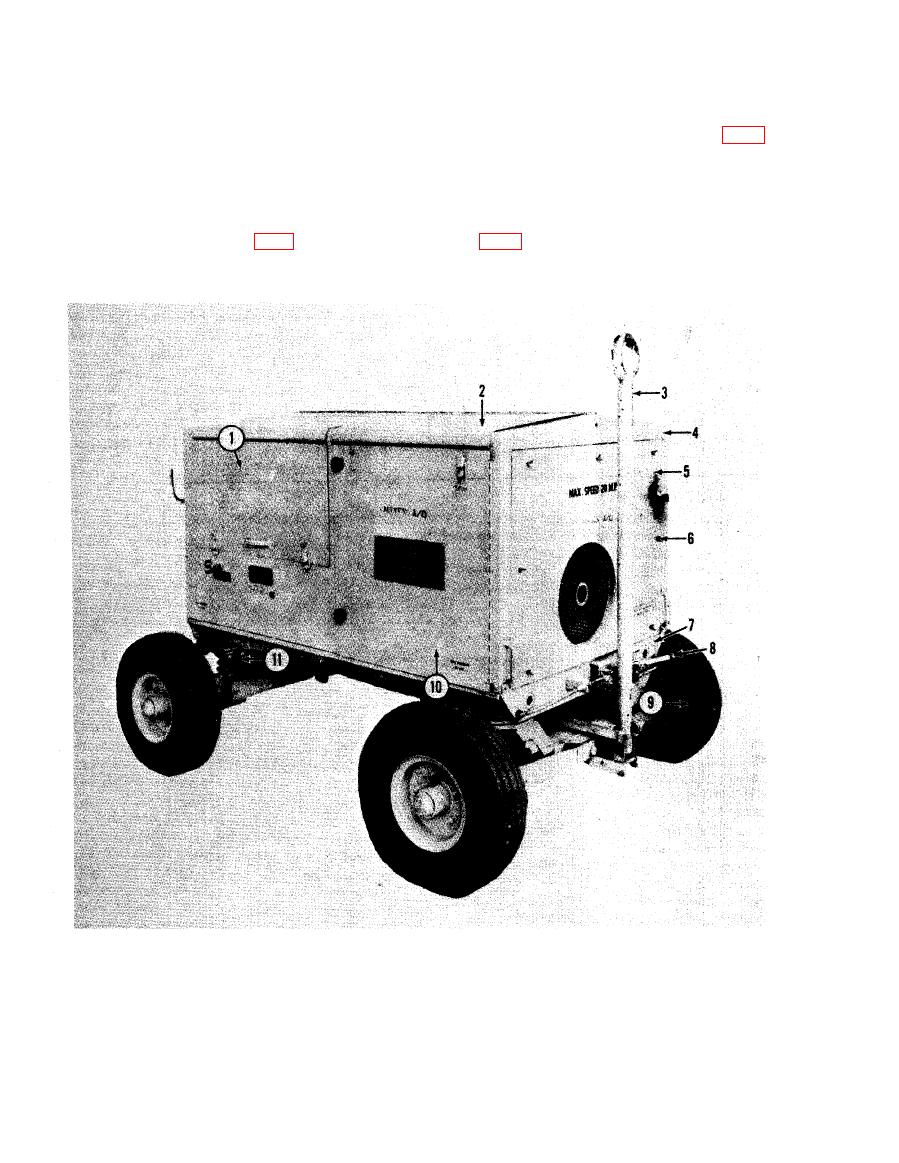
Figure 1. Aircraft hydraulic test stand, three-quarter, right front view. |
|
||
| ||||||||||
|
|
 lutions per minute) by a centrifugal fly-weight
door assembly (2), front right door assembly
governor which adjusts the throttle to compen-
(10), and left front door assembly (1, fig. 2)
sate for changes in engine load. A handcrank,
are opened to gain access to the engine com-
for manually cranking the engine, is secured
partment.
to the frame in the engine compartment of the
d. Hydraulic Reservoir. The hydraulic reser-
test stand. Controls for operating the engine
voir is mounted in the upper left rear corner
are made accessible by opening the control
of the housing assembly with the reservoir fill
panel door assembly (1, fig. 1). The f rent top
cap (4, fig. 2) extending through the rear top
5
Front panel assembly
1
Control panel door assembly
9 Pneumatic tire
10 Right front door assembly
2
Front top door assembly
6
Thumbscrew
7
Frame assembly
11 Spring
3
Drawbar assembly
8
Brake lever assembly
4
Housing assembly
4
AGO 5742A
|
|
Privacy Statement - Press Release - Copyright Information. - Contact Us |