 |
|||
|
|
|||
|
Page Title:
Drawbar and Steering Arm Assemblies |
|
||
| ||||||||||
|
|
 c. Installation.
b. Installation.
(1) Install the sleeve bearing (85, fig. 14)
(1) Position the wheel on the hub (51) and
in the support and arm assembly (70).
secure with the 5 lockwashers (31)
(2) Position the steering arm assembly
and 5 hex nuts (30).
(14) on the support and arm assembly
(2) Install the remaining wheels in a
similar manner.
and insert the shear bolt (18) in the
alined holes of the arm and sleeve
bearing. Install the two thrust wash-
a. Removal.
ers (17), nut (16) and insert cotter
pin (15) in the shear bolt.
(1) Remove the hex nut (20, fig. 14) and
bolt (21) that secure the latch (19) to
(3) Insert the 2 tie rod ends (5) in the
the steering arm assembly (14) and
s t e e r i n g arm assembly and secure
remove the latch.
with the 2 nuts (2) and 2 cotter pins
(1).
(2) Remove the retaining ring (13) and
headed grooved pin (12) that secure
(4) Position the drawbar assembly (11) in
t h e drawbar assembly (11) to the
the steering arm assembly and install
steering arm assembly and remove the
the headed grooved pin ( 12) and the
drawbar.
retaining ring (13).
(3) Remove the 2 cotter pins (1), and nuts
(5) Place the latch (19) on the steering
(2) that secure the 2 tie rod ends (5)
arm and install the bolt (21) and hex
to the steering arm assembly and lift
nut (20).
the tie rod ends out of the arm.
(4) Remove the cotter pin (15), nut (16),
two thrust washers (17), and shear
a. Removal.
bolt (18) from the steering arm as-
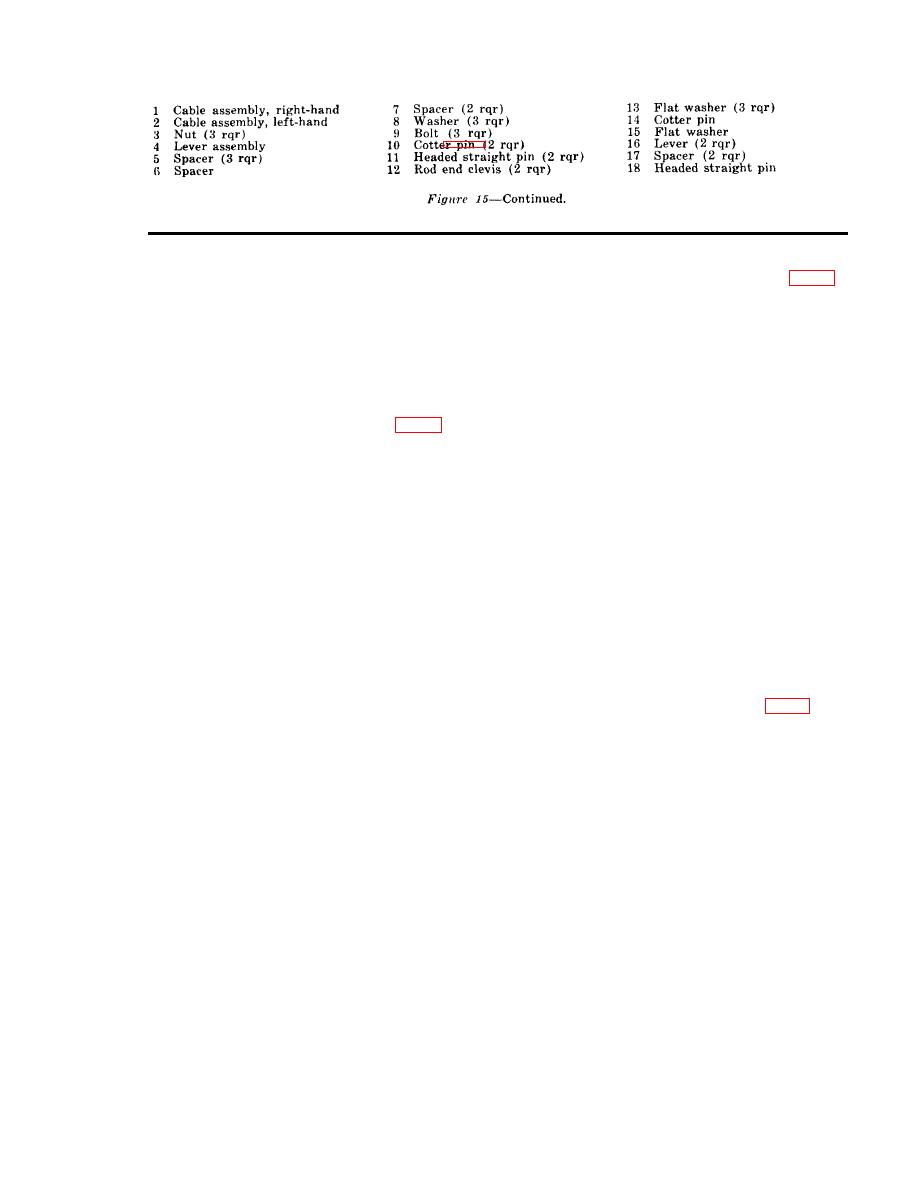
(1) Remove the 2 hex nuts (3, fig. 15) that
sembly and remove the steering arm
secure the 2 cable assemblies ( 1 and
from the support and arm assembly
2) to the 2 rod end clevises (12) and
(70).
pull cable ends out of the clevises.
(5) Remove the sleeve bearing (85) from
(2) Remove the 3 bolts (9), 3 spacers (5),
the support and arm assembly.
2 spacers (7), the spacer (6) and 3
lockwashers (8) that secure the lever
b. Cleaning and Inspection.
assembly (4) to the frame and remove
(1) Clean all parts in an approved cleaning
the lever assembly.
solvent and dry thoroughly.
(2) Inspect the drawbar and steering arm
b. Cleaning and Inspection.
assembly for cracks, breaks, and dis-
(1) Clean the break lever assembly with
tortion.
an approved cleaning solvent and dry
(3) Inspect the thrust washer and sleeve
thoroughly.
bearing for nicks, burrs, distortion,
(2) Inspect the brake lever assembly for
and excessive wear.
cracks, breaks, and distortion. Check
(4) Inspect all attaching hardware for dis-
to see that the lever operates free
tortion and damaged threads.
without binding. Replace a defective
brake lever assembly.
(5) Replace all defective parts.
AGO 5742A
|
|
Privacy Statement - Press Release - Copyright Information. - Contact Us |
