 |
|||
|
|
|||
|
Page Title:
Section VI. RUNNING GEAR ASSEMBLY |
|
||
| ||||||||||
|
|
 b . Pressure Gage Replacement.
(2) Install the pump-to-low pressure filter
hose assembly (4, fig. 12), pump-to-
(1) Removal.
high pressure hose assembly (8), fluid
(a) Close the reservoir shutoff valve
pressure gage-to-dampener hose as-
(12, fig. 9).
sembly (37), and the pressure selector
(b) Disconnect the hose from the back
valve-to-filter gage hose assembly
of the filter pressure gage (6).
(44).
(c) Remove the 3 nuts and 3 screws that
(3) Install the drain assembly in the bot-
secure the filter pressure gage to
the panel and remove the gage.
tom of the reservoir and fill the reser-
(d) Remove the fluid pressure gage (3)
voir (par. 9).
in a similar manner.
(2) Installation.
a. Testing Pressure Gages.
(a) Position the filter pressure gage (6)
(1) Connect a pressure gage of known ac-
in the panel (1) and secure with the
curacy to the filter pressure gage tap
3 screws and 3 nuts.
(26, fig. 9).
(b) Connect the hose to the back of the
filter pressure gage.
(2) Start the test stand (par. 41) and
(c) Open the reservoir shutoff valve
compare the readings of both the test
(12).
gage and the filter pressure gage (6).
(d) Install the fluid pressure gage in a
Replace a defective gage as outlined
similar manner.
below.
VI. RUNNING GEAR ASSEMBLY
Section
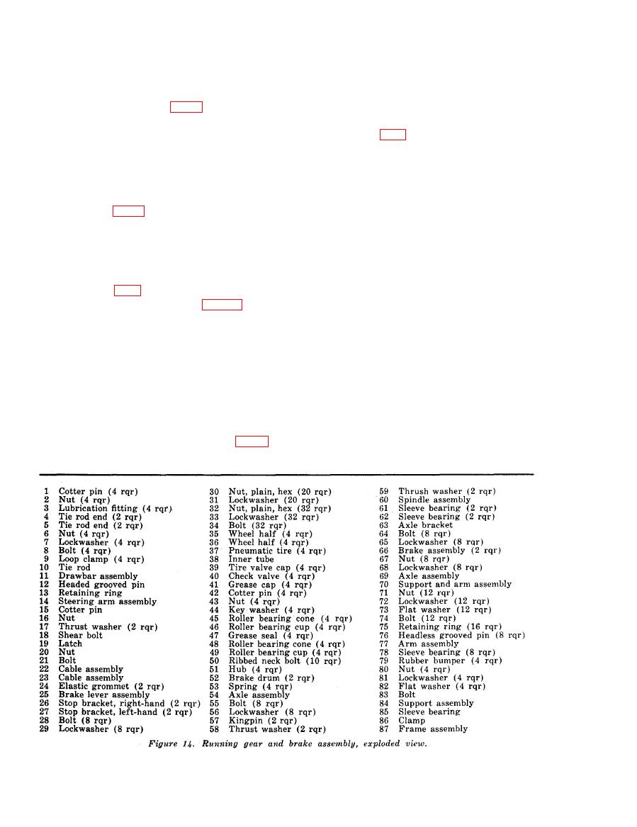
the wheel to the hub (51) and remove
74. Wheels
the wheel.
a. Removal.
(1) Remove the 5 hex nuts (30, fig. 14)
(2) Remove the remaining wheels in a
similar manner.
and 5 lockwashers (31) that secure
AGO 5742A
|
|
Privacy Statement - Press Release - Copyright Information. - Contact Us |