 |
|||
|
|
|||
|
|
|||
| ||||||||||
|
|
 movable point to obtain the proper
h. Timing and Installation.
clearance of 0.015 inch.
(1) Remove the spark plug from the num-
ber 1 cylinder (par. 114).
(3) Tighten the 2 screws (14) and rein-
(2) Crank the engine slowly until air
spect the clearance.
blows from the spark plug hole, indi-
(4) Reassemble and install the magneto
cating start of the compression stroke.
as outlined in g and h below.
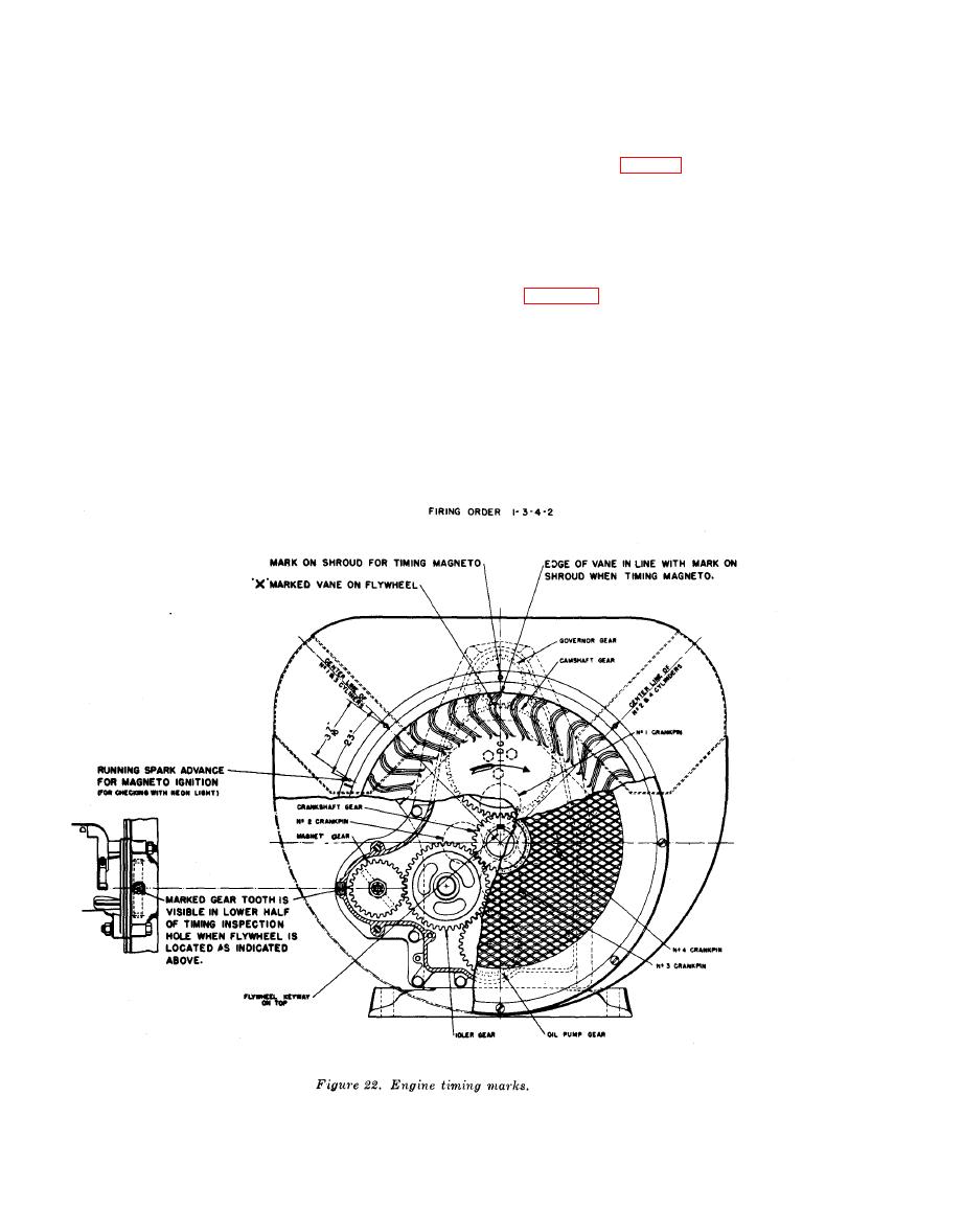
Continue cranking until the edge of
g. Reassembly.
the marked flywheel vane is in line
(1) Install the distributor rotor (12, fig.
with the mark on the shroud as shown
21) on the spur gear (39).
in figure 22.
(2) Position the end cap (9) on the mag-
(3) Remove the timing hole plug (18, fig.
neto housing (50) and secure with
11) from the gear cover (19).
the 2 screws (10) and 2 screws (11).
(4) Turn the magneto drive gear clockwise
(3) Insert the capacitor (1) in the end
so that when the magneto is positioned
cap and secure with the two screws
on the engine, its drive gear will en-
(2).
gage the idler gear with the marked
AGO 5742A
|
|
Privacy Statement - Press Release - Copyright Information. - Contact Us |