 |
|||
|
|
|||
|
|
|||
| ||||||||||
|
|
 TM 55-4920-335-14
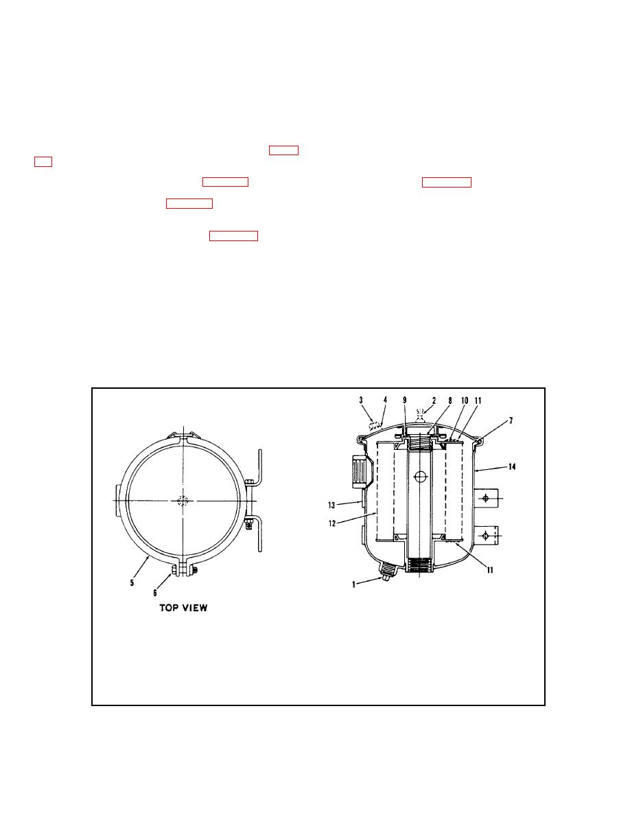
g. Install cover, clamping ring (5), and tighten clamping
CAUTION
ring screw (6). Install drain plug (1). Remove filler plug (3) and
gasket (4). Fill filter with hydraulic fluid and reinstall filler plug
The Test Stand shall never be operated
and gasket.
with a filter inlet vacuum reading greater
than 16 inches Hg.
4-10. SERVICING ENGINE FUEL PUMP. An engine fuel
4-9. SERVICING LOW PRESSURE FILTER. Replace a
pump may fail because of dirt in the head. This can be
clogged or dirty filter element in low pressure filter (7, figure
cleaned as follows:
1-3) as follows:
a. Using a file, scratch an indicating mark across a point
a.
Close reservoir shuto ff valve (1, figure 3-1).
of union of head (7, figure 4-2) and mounting bracket (23).
Remove the two fuel lines.
b. Remove drain plug (1, figure 4-1) and drain hydraulic
fluid from filter case.
b. Remove six screws (6) from fuel head and remove
head (7).
c. Loosen clamping ring screw (6, figure 4-1) to allow
removal of clamping ring (5). Remove cover from body and
c. Unscrew dome bolt (1) and disassemble dome (3),
cover assembly (14).
gasket (4), and filter screen (5).
d. Remove element retainer assembly (8), end guide
d. Wash out sediment cavities of head (7) using gasoline
(10), and element gaskets (11). Lift element (12) out of body.
and a fine brush. Be careful not to damage valve assemblies
in lower cavity of head.
e. Thoroughly clean body and cover assembly (14).
Carefully inspect gaskets (7, 9, and 11) and replace with new
e. Hand crank engine to a position where diaphragm
gaskets if required. Install new filter element (12) in body and
(14) is laying flat across face of mounting bracket (23). Place
cover assembly (14).
fuel head (7) back in position so that indicating marks are in
line and thread screws (6) through head and into mounting
f. Install gasket (11), end guide (10), and secure with
element retainer assembly (8).
1.
Drain Plug
8.
Element R etainer Assembly
2.
Vent
9.
Gasket
3.
Filler Plug
10.
End Guide
4.
Gasket
11.
Gasket
5.
Clamp Ring
12.
Element
6.
Clamp Ring Screw
13.
Mounting Bracket
7.
Gasket
14.
Body and Cover
Figure 4-1. Low Pressure Filter Assembly
4-3
|
|
Privacy Statement - Press Release - Copyright Information. - Contact Us |
