 |
|||
|
|
|||
|
Page Title:
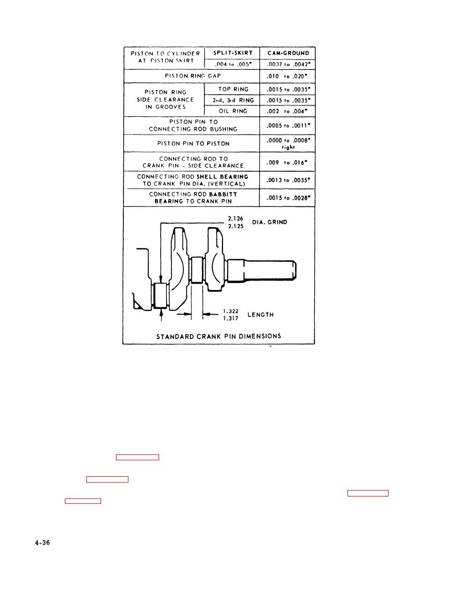
Figure 4-24. Piston, Ring, and Rod Clearances |
|
||
| ||||||||||
|
|
 TM 55-4920-405-13&P
Figure 4-24.
Piston, Ring, and Rod Clearances
.--.--
NOTE
CAUT.ION
----
-
You may find either babbit cast bearing
connecting rods or shell bearing con-
Identical numbers are stamped on the
necting rods in your engine. You can
side of each connecting rod and its cap.
use shell bearing connecting rods to re-
Make sure these numbers are both on
place babbit cast bearing connecting rods.
the same side of the connecting rod when
mounted in the crankcase assembly.
7.
When you install the idler gear on
the crankcase, allow a 0.003 to
Make sure that the oil hole in the con-
0.004 inch clearance between the
necting rod cap is facing toward the oil
idler gear and the stud collar.
spray nozzle. (See figure 4-26.) Make
8.
When you install the crankshaft
sure that the lugs on the connecting rod
gear, turn the crankshaft so that
bearing halves are both on the same
the timing marks on the crank-
side. (See figure 4-19.) Install new
shaft gear and the camshaft gear
nuts on the connecting rod bolts and
are aligned. (See figure 4-16.)
torque the nuts to 26 to 32 foot-pounds.
If you do not align the timing
See figure 4-24 for the proper clear-
marks, the engine will run poorly
ance between the bearing and the crank
or not at all.
pin.
|
|
Privacy Statement - Press Release - Copyright Information. - Contact Us |
