
TM 5-2350-378-23&P
0015
HYDRAULIC OIL OVERHEATS - Continued
1
T01356HDC
Figure 40.
Directional Control Valve (DCV) Bank.
d.
Using LINE UP or LINE DOWN button (Figure 39, Item 3) on HDC control box, select V5 on HDC display
(Figure 39, Item 2).
e.
Using CHANGE POSITION button (Figure 39, Item 4), close V5 on HDC display (Figure 39, Item 2).
f.
Repeat last two steps for V12, V13, and V19; closing V12 and V13, and opening V19.
g.
Start engine.
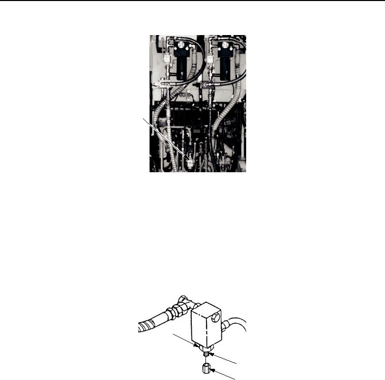
h.
Remove cap (Figure 41, Item 3) from suspension relief valve adjusting shaft (Figure 41, Item 2) and
loosen jam nut (Figure 41, Item 1).
1
2
3
T01357HDC
Figure 41.
Suspension Relief Valve.
(1)
Observe transducer T-13 hydraulic pressure on HDC display (Figure 39, Item 1).
(2)
Turn adjusting shaft (Figure 41, Item 2) clockwise to increase pressure or counterclockwise to
decrease pressure, as necessary, to obtain desired pressure.
(3)
Tighten jam nut (Figure 41, Item 1) and replace cap (Figure 41, Item 3).
i.
Stop engine and relieve hydraulic pressure
j.
Manually open ejector ball valve V23 (Figure 40, Item 1) on DCV bank.
03/15/2011Rel(1.8)root(tswp)wpno(T00013)