
TM 5-2350-378-23&P
0042
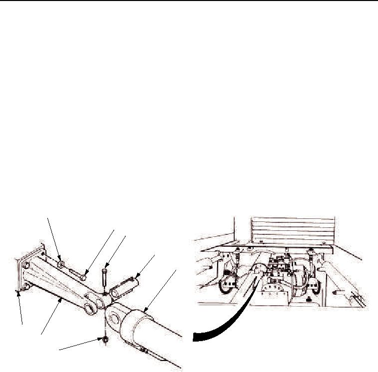
REMOVAL
1.
Support rear ejector cylinder end (Figure 1, Item 5) and remove screw (Figure 1, Item 3), locknut
(Figure 1, Item 6), and pin (Figure 1, Item 4) from ejector cylinder (Figure 1, Item 5) and bracket
(Figure 1, Item 7). Discard locknut.
2.
Remove four machine bolts (Figure 1, Item 2), washers (Figure 1, Item 1), and bracket (Figure 1, Item 7) from
hull (Figure 1, Item 8). Discard machine bolts.
END OF TASK
INSTALLATION
NOTE
Apply lubricating oil to threads of screws prior to installation.
1.
Install bracket (Figure 1, Item 7) on hull (Figure 1, Item 8) with four washers (Figure 1, Item 1) and new machine
bolts (Figure 1, Item 2). Tighten four machine bolts (Figure 1, Item 2) to 123-135 lb-ft (167-183 Nm).
2.
Install rear ejector cylinder end (Figure 1, Item 5) on bracket (Figure 1, Item 7) with pin (Figure 1, Item 4), screw
(Figure 1, Item 3), and locknut (Figure 1, Item 6). Tighten screw (Figure 1, Item 3) to 20-22 lb-ft (27-30 Nm).
1
2
3
4
5
8
7
6
M0067HDC
Figure 1. Hull/Ejector Interference Modification Removal/Installation.
END OF TASK
FOLLOW-ON MAINTENANCE
Install rear floor plates (TM 5-2350-262-20).
END OF TASK
END OF WORK PACKAGE
03/15/2011Rel(1.8)root(maintwp)wpno(M00019)